Nissan Titan. Manual - part 324


  Index      Nissan     Nissan Titan (2014 year) - Service and Repair Manual


Search            


Content   ..  322  323  324  325   ..


Nissan Titan. Manual - part 324


EM-100

< UNIT DISASSEMBLY AND ASSEMBLY >

ENGINE UNIT

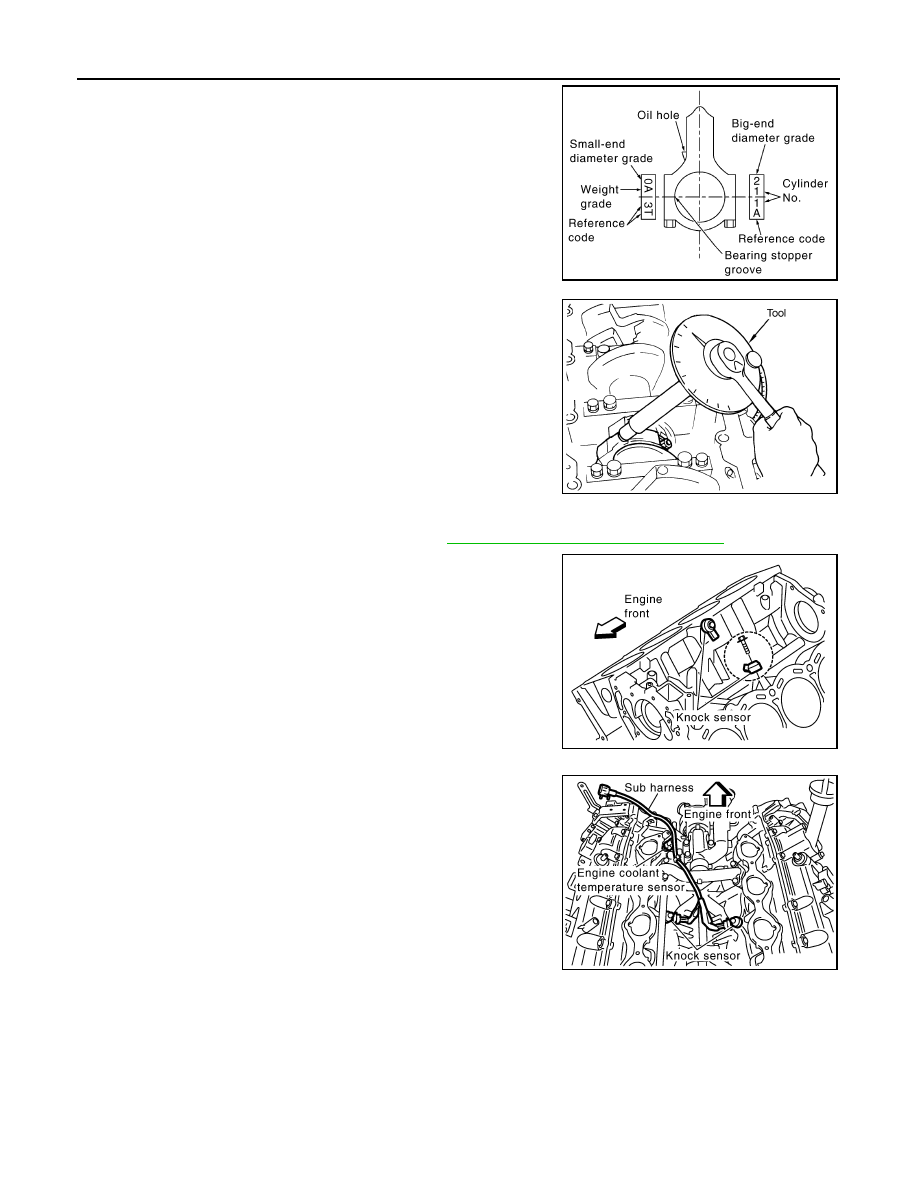
14. Install connecting rod cap.

• Match the stamped cylinder number marks on the connecting

rod with those on the cylinder cap to install.   

15. Tighten connecting rod bolts using Tool.

• Apply engine oil to threads and seats of connecting rod bolts. 

• After tightening bolts, make sure the crankshaft rotates smoothly. 

• Check connecting rod side clearance. Refer to 

EM-101, "Inspection After Disassembly"

.

16. Install knock sensors.

CAUTION:

If knock sensor is dropped, replace it with a new one.

• Make sure that there is no foreign material on the cylinder

block mating surface and the back surface of knock sensor. 

• Install it with its connector facing the center of the cylinder

block side. 

• Do not tighten knock sensor bolts while holding connector.   

• Make sure knock sensor does not interfere with other parts.

• Position the sub-harness as shown before installing intake

manifold. 

17. Installation of the remaining components is in the reverse order of removal.
18. Remove engine assembly from engine stand.

KBIA2536E

Tool number

: KV10112100 (BT-8653-A)

Connecting rod bolts
Step 1

: 29.4 N·m (3.0 kg-m, 22 ft-lb)

Step 2

: Loosen to 0 N·m

Step 3

: 19.6 N·m (1.5 kg-m, 11 ft-lb)

Step 4

: 90

° clockwise

WBIA0627E

KBIA2493E

KBIA2549E

ENGINE UNIT

EM-101

< UNIT DISASSEMBLY AND ASSEMBLY >

C

D

E

F

G

H

I

J

K

L

M

A

EM

N

P

O

19. Install drive plate. 

• Align dowel pin of crankshaft rear end with pin holes of each

part to install.

• Install drive plate, reinforcement plate and pilot converter (if

not installed in step 4) as shown.

• Face the chamfered or rounded edge side to the crankshaft.

Inspection After Disassembly

INFOID:0000000009886447

CRANKSHAFT END PLAY

• Move the crankshaft fully forward and backward and measure the

clearance between the thrust bearings and crankshaft arm using

suitable tool.

• If measured value exceeds the repair limit, replace the thrust bear-

ings, and measure again. If it still exceeds the repair limit, replace

crankshaft also.

CONNECTING ROD SIDE CLEARANCE

• Measure side clearance between the connecting rod and crank-

shaft arm using suitable tool.

• If measured value exceeds the repair limit, replace the connecting

rod bearings, and measure again. If it still exceeds the repair limit,

replace the crankshaft also.

PISTON AND PISTON PIN CLEARANCE

Piston Pin Hole Diameter

KBIA2494E

KBIA2537E

Standard

: 0.10 - 0.26 mm (0.0039 - 0.0102 in)

Limit

: 0.30 mm (0.0118 in)

PBIC0114E

Standard

: 0.20 - 0.40 mm (0.0079 - 0.0157 in)

Limit

: 0.40 mm (0.0157 in)

PBIC0115E

EM-102

< UNIT DISASSEMBLY AND ASSEMBLY >

ENGINE UNIT

• Measure diameter of piston pin hole using suitable tool.

Piston Pin Diameter 

• Measure diameter of piston pin using suitable tool.

Piston and Piston Pin Clearance

(Piston pin clearance) = (Piston pin hole diameter) – (Piston pin

diameter)

• If clearance exceeds specification, replace either or both the pis-

ton/piston pin assembly and the connecting rod assembly with ref-

erence to the specification of each part.

• Use the piston selection table to replace piston/piston pin assem-

bly. Refer to 

EM-111, "How to Select Piston and Bearing"

.

• Use the connecting rod bearing selection table to replace connect-

ing rod. Refer to 

EM-111, "How to Select Piston and Bearing"

.

NOTE:

The connecting rod small end grade and piston pin hole (piston

pin) grade are provided only for the parts installed at the plant. For

service parts, no grades can be selected (only 0 grade is avail-

able). 

• Follow "Connecting Rod Bushing Oil Clearance (Small End)" for

the values for each grade at the plant.

PISTON RING SIDE CLEARANCE

Standard

: 21.993 - 21.999 mm (0.8659 - 0.8661 in)

PBIC0116E

Standard

: 21.989 - 21.995 mm (0.8657 - 0.8659 in)

PBIC0117E

Standard

: 0.002 - 0.006 mm (0.0001 - 0.0002 in)

KBIA2496E

KBIA2536E

ENGINE UNIT

EM-103

< UNIT DISASSEMBLY AND ASSEMBLY >

C

D

E

F

G

H

I

J

K

L

M

A

EM

N

P

O

• Measure side clearance of the piston ring and piston ring groove

using suitable tool.

• If out of specification, replace piston and/or piston ring assembly.

PISTON RING END GAP

• Check if the diameter of the cylinder bore is within specification.

Refer to 

EM-118, "Standard and Limit"

.

• Insert the piston ring into the middle of the cylinder using the pis-

ton, and measure the gap.

• If out of specification, replace piston ring. 

CONNECTING ROD BEND AND TORSION

• Check connecting rod alignment using suitable tool.

• If measurement exceeds the limit, replace connecting rod assem-

bly.

Standard:

Top ring

: 0.035 - 0.085 mm (0.0014 - 0.0033 in)

2nd ring

: 0.030 - 0.070 mm (0.0012 - 0.0028 in)

Oil ring

: 0.015 - 0.185 mm (0.0006 - 0.0073 in)

Limit:

Top ring

: 0.11 mm (0.0043 in)

2nd ring

: 0.10 mm (0.0039 in)

SEM024AA

Standard

Top ring

: 0.23 - 0.33 mm (0.0091 - 0.0130 in)

2nd ring

: 0.25 - 0.40 mm (0.0098 - 0.0157 in)

Oil ring

: 0.20 - 0.60 mm (0.0079 - 0.0236 in)

Limit:

Top ring

: 0.56 mm (0.0220 in)

2nd ring

: 0.52 mm (0.0205 in)

Oil ring

: 0.96 mm (0.0378 in)

PBIC0118E

Limit:

Bend

: 0.15 mm (0.0059 in) per 100 mm (3.94 in) length

Torsion

: 0.30 mm (0.0118 in) per 100 mm (3.94 in) length

SEM003F

SEM038F


Content   ..  322  323  324  325   ..