Nissan Titan. Manual - part 292
IGNITION SIGNAL
EC-469
< DTC/CIRCUIT DIAGNOSIS >
[VK56DE]
C
D
E
F
G
H
I
J
K
L
M
A
EC
N
P
O
IGNITION SIGNAL
Component Description
INFOID:0000000009886922
IGNITION COIL & POWER TRANSISTOR
The ignition signal from the ECM is sent to and amplified by the power transistor. The power transistor turns
ON and OFF the ignition coil primary circuit. This ON/OFF operation induces the proper high voltage in the coil
secondary circuit.
Diagnosis Procedure
INFOID:0000000009886923
1.
CHECK ENGINE START
Turn ignition switch OFF, and restart engine.
Is engine running?
Yes or No
Yes (With CONSULT)>>GO TO 2.
Yes (Without CONSULT)>>GO TO 3.
No
>> GO TO 4.
2.
CHECK OVERALL FUNCTION
With CONSULT
1. Perform “POWER BALANCE” in “ACTIVE TEST” mode with CONSULT.
2. Make sure that each circuit produces a momentary engine speed drop.
OK or NG
OK
>> INSPECTION END
NG
>> GO TO 10.
3.
CHECK OVERALL FUNCTION
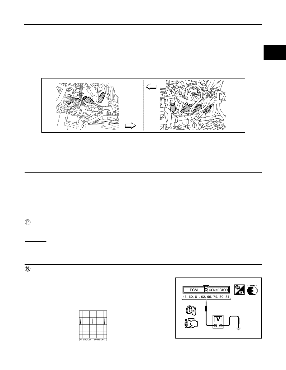
Without CONSULT
1. Let engine idle.
2. Read the voltage signal between ECM terminals 46, 60, 61, 62,
65, 79, 80, 81 and ground with an oscilloscope.
3. Verify that the oscilloscope screen shows the signal wave as
shown below.
NOTE:
The pulse cycle changes depending on rpm at idle.
OK or NG
1.
Ignition coils (with power transistor)
(bank 2)
2.
Ignition coils (with power transistor)
(bank 1)
BBIA0777E
PBIB2094E
PBIB0044E