Nissan Titan. Manual - part 287
 

  Index      Nissan     Nissan Titan (2014 year) - Service and Repair Manual


Search            


Content   ..  285  286  287  288   ..


Nissan Titan. Manual - part 287


P2138 APP SENSOR

EC-449

< DTC/CIRCUIT DIAGNOSIS >

[VK56DE]

C

D

E

F

G

H

I

J

K

L

M

A

EC

N

P

O

Diagnosis Procedure

INFOID:0000000009886903

1.

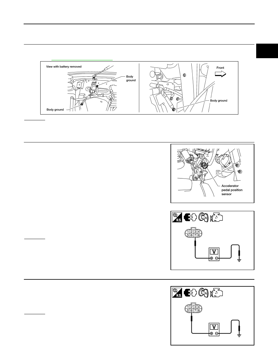
CHECK GROUND CONNECTIONS

1. Turn ignition switch OFF.

2. Loosen and retighten three ground screws on the body.

Refer to 

EC-154, "Ground Inspection"

.

OK or NG

OK

>> GO TO 2.

NG

>> Repair or replace ground connections.

2.

CHECK APP SENSOR 1 POWER SUPPLY CIRCUIT

1. Disconnect accelerator pedal position (APP) sensor harness

connector.

2. Turn ignition switch ON.

3. Check voltage between APP sensor terminal 7 and ground with

CONSULT or tester.

OK or NG

OK

>> GO TO 3.

NG

>> Repair open circuit or short to ground or short to power

in harness or connectors.

3.

CHECK APP SENSOR 2 POWER SUPPLY CIRCUIT-I

1. Turn ignition switch ON.

2. Check voltage between APP sensor terminal 6 and ground with

CONSULT or tester.

OK or NG

OK

>> GO TO 8.

NG

>> GO TO 4.

BBIA0354E

BBIA0361E

Voltage: Approximately 5V

JPBIA5715ZZ

Voltage: Approximately 5V

JSBIA1930ZZ

EC-450

< DTC/CIRCUIT DIAGNOSIS >

[VK56DE]

P2138 APP SENSOR

4.

CHECK APP SENSOR 2 POWER SUPPLY CIRCUIT-II

1. Turn ignition switch OFF.

2. Disconnect ECM harness connector.

3. Check harness continuity between APP sensor terminal 6 and ECM terminal 91.

Refer to Wiring Diagram.

OK or NG

OK

>> GO TO 5.

NG

>> Repair open circuit in harness or connectors.

5.

CHECK APP SENSOR 2 POWER SUPPLY CIRCUIT-III

Check harness for short to power and short to ground, between the following terminals

OK or NG

OK

>> GO TO 6.

NG

>> Repair short to ground or short to power in harness connectors.

6.

CHECK THROTTLE POSITION SENSOR

Refer to 

EC-451, "Component Inspection"

.

OK or NG

OK

>> GO TO 12.

NG

>> GO TO 7.

7.

REPLACE ELECTRIC THROTTLE CONTROL ACTUATOR

1. Replace the electric throttle control actuator.

2. Perform 

EC-128, "Throttle Valve Closed Position Learning"

.

3. Perform 

EC-129, "Idle Air Volume Learning"

.

>> INSPECTION END

8.

CHECK APP SENSOR GROUND CIRCUIT FOR OPEN AND SHORT

1. Turn ignition switch OFF.

2. Disconnect ECM harness connector.

3. Check harness continuity between ECM terminal 82 and APP sensor terminal 1, ECM terminal 83 and

APP sensor terminal 3.

Refer to Wiring Diagram.

4. Also check harness for short to ground and short to power.
OK or NG

OK

>> GO TO 9.

NG

>> Repair open circuit or short to ground or short to power in harness or connectors.

9.

CHECK APP SENSOR INPUT SIGNAL CIRCUIT FOR OPEN AND SHORT

1. Check harness continuity between ECM terminal 106 and APP sensor terminal 2, ECM terminal 98 and

APP sensor terminal 5.

Refer to Wiring Diagram.

2. Also check harness for short to ground and short to power.

Continuity should exist.

ECM terminal

Sensor terminal

Reference Wiring Diagram

47

Electric throttle control actuator terminal 2

EC-88, "Wiring Diagram"

91

APP sensor terminal 6

Continuity should exist.

Continuity should exist.

P2138 APP SENSOR

EC-451

< DTC/CIRCUIT DIAGNOSIS >

[VK56DE]

C

D

E

F

G

H

I

J

K

L

M

A

EC

N

P

O

OK or NG

OK

>> GO TO 10.

NG

>> Repair open circuit or short to ground or short to power in harness or connectors.

10.

CHECK ACCELERATOR PEDAL POSITION SENSOR

Refer to 

EC-451, "Component Inspection"

.

OK or NG

OK

>> GO TO 12.

NG

>> GO TO 11.

11.

REPLACE ACCELERATOR PEDAL ASSEMBLY

1. Replace the accelerator pedal assembly.

2. Perform 

EC-128, "Accelerator Pedal Released Position Learning"

.

3. Perform 

EC-128, "Throttle Valve Closed Position Learning"

.

4. Perform 

EC-129, "Idle Air Volume Learning"

.

>> INSPECTION END

12.

CHECK INTERMITTENT INCIDENT

Refer to 

GI-39, "How to Check Terminal"

 and 

GI-42, "Intermittent Incident"

.

>> INSPECTION END

Component Inspection

INFOID:0000000009886904

ACCELERATOR PEDAL POSITION SENSOR

1. Reconnect all harness connectors disconnected.
2. Turn ignition switch ON.
3. Check voltage between ECM terminals 106 (APP sensor 1 sig-

nal), 98 (APP sensor 2 signal) and ground under the following

conditions.

4. If NG, replace accelerator pedal assembly and go to next step.
5. Perform 

EC-128, "Accelerator Pedal Released Position Learning"

.

6. Perform 

EC-128, "Throttle Valve Closed Position Learning"

.

7. Perform 

EC-129, "Idle Air Volume Learning"

.

Terminal

Accelerator pedal

Voltage

106
 (Accelerator pedal position 
sensor 1)

Fully released

0.5 - 1.0V

Fully depressed

4.2 - 4.8V

98
(Accelerator pedal position 
sensor 2)

Fully released

0.25 - 0.5V

Fully depressed

2.0 - 2.5V

MBIB0023E

EC-452

< DTC/CIRCUIT DIAGNOSIS >

[VK56DE]

ASCD BRAKE SWITCH

ASCD BRAKE SWITCH

Component Description

INFOID:0000000009886909

When the brake pedal is depressed, ASCD brake switch is turned

OFF and stop lamp switch is turned ON. ECM detects the state of

the brake pedal by this input of two kinds (ON/OFF signal).

Refer to 

EC-28

 for the ASCD function.

Diagnosis Procedure

INFOID:0000000009886910

1.

CHECK OVERALL FUNCTION-I

 With CONSULT

1. Turn ignition switch ON.

2. Select “BRAKE SW 1” in “DATA MONITOR” mode with CONSULT.

3. Check “BRAKE SW 1” indication under the following conditions.

 Without CONSULT

1. Turn ignition switch ON.

2. Check voltage between ECM terminal 108 and ground under the

following conditions.

OK or NG

OK

>> GO TO 2.

NG

>> GO TO 3.

2.

CHECK OVERALL FUNCTION-II

 With CONSULT

Check “BRAKE SW 2” indication in “DATA MONITOR” mode. 

 Without CONSULT

Check voltage between ECM terminal 101 and ground under the following conditions.

BBIA0087E

CONDITION

INDICATION

Brake pedal: Slightly depressed

OFF

Brake pedal: Fully released

ON

CONDITION

VOLTAGE

Brake pedal: Slightly depressed

Approximately 0V

Brake pedal: Fully released

Battery voltage

MBIB0061E

CONDITION

INDICATION

Brake pedal: Fully released

OFF

Brake pedal: Slightly depressed

ON


Content   ..  285  286  287  288   ..