Nissan Titan. Manual - part 281


  Index      Nissan     Nissan Titan (2014 year) - Service and Repair Manual


Search            


Content   ..  279  280  281  282   ..


Nissan Titan. Manual - part 281


P2096, P2097, P2098, P2099 A/F SENSOR 1

EC-425

< DTC/CIRCUIT DIAGNOSIS >

[VK56DE]

C

D

E

F

G

H

I

J

K

L

M

A

EC

N

P

O

2. Turn ignition switch OFF.

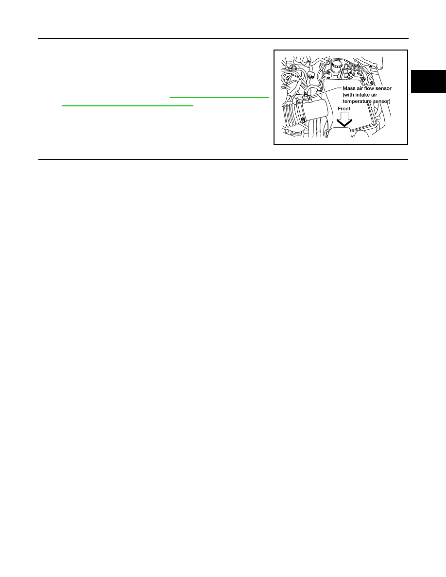
3. Disconnect mass air flow sensor harness connector.

4. Restart engine and let it idle for at least 5 seconds.

5. Stop engine and reconnect mass air flow sensor harness con-

nector.

6. Make sure DTC P0102 is displayed.

7. Erase the DTC memory. Refer to 

EC-49, "CONSULT Function"

or 

EC-46, "On Board Diagnosis Function"

.

8. Make sure DTC P0000 is displayed.

>> GO TO 16.

16.

CONFIRM A/F ADJUSTMENT DATA

1. Turn ignition switch OFF and then ON.

2. Select “A/F ADJ-B1” and “A/F ADJ-B2” in “DATA MONITOR” mode with CONSULT.

3. Make sure that “0.000” is displayed on CONSULT screen.

>> INSPECTION END

BBIA0368E

EC-426

< DTC/CIRCUIT DIAGNOSIS >

[VK56DE]

P2100, P2103 THROTTLE CONTROL MOTOR RELAY

P2100, P2103 THROTTLE CONTROL MOTOR RELAY

Component Description

INFOID:0000000009886867

Power supply for the throttle control motor is provided to the ECM via throttle control motor relay. The throttle

control motor relay is ON/OFF controlled by the ECM. When the ignition switch is turned ON, the ECM sends

an ON signal to throttle control motor relay and battery voltage is provided to the ECM. When the ignition

switch is turned OFF, the ECM sends an OFF signal to throttle control motor relay and battery voltage is not

provided to the ECM.

On Board Diagnosis Logic

INFOID:0000000009886868

These self-diagnoses have the one trip detection logic.

FAIL-SAFE MODE

When the malfunction is detected, ECM enters fail-safe mode and the MIL lights up.

DTC Confirmation Procedure

INFOID:0000000009886869

NOTE:

If DTC Confirmation Procedure has been previously conducted, always perform the following before conduct-

ing the next step. 
1. Turn ignition swich OFF and wait at least 10 seconds.
2. Turn ignition swich ON.
3. Turn ignition swich OFF and wait at least 10 seconds.

PROCEDURE FOR DTC P2100

1. Turn ignition switch ON and wait at least 2 seconds.

2. Start engine and let it idle for 5 seconds.

3. Check DTC.

4. If DTC is detected, go to 

EC-426, "Diagnosis Procedure"

.

PROCEDURE FOR DTC P2103 

TESTING CONDITION:

Before performing the following procedure, confirm that battery voltage is more than 8V.

1. Turn ignition switch ON and wait at least 1 second.

2. Check DTC.

3. If DTC is detected, go to 

EC-426, "Diagnosis Procedure"

.

Diagnosis Procedure

INFOID:0000000009886870

1.

CHECK THROTTLE CONTROL MOTOR RELAY POWER SUPPLY CIRCUIT-I

1. Turn ignition switch OFF.

DTC No.

Trouble diagnosis name

DTC detecting condition

Possible cause

P2100
2100

Throttle control motor 
relay circuit open

ECM detects a voltage of power source 
for throttle control motor is excessively 
low.

• Harness or connectors

(Throttle control motor relay circuit is open)

• Throttle control motor relay

P2103
2103

Throttle control motor 
relay circuit short

ECM detect the throttle control motor re-
lay is stuck ON.

• Harness or connectors

(Throttle control motor relay circuit is shorted)

• Throttle control motor relay

Engine operating condition in fail-safe mode

ECM stops the electric throttle control actuator control, throttle valve is maintained at a fixed opening (approx. 5 degrees) by the return 
spring.

P2100, P2103 THROTTLE CONTROL MOTOR RELAY

EC-427

< DTC/CIRCUIT DIAGNOSIS >

[VK56DE]

C

D

E

F

G

H

I

J

K

L

M

A

EC

N

P

O

2. Check voltage between ECM terminal 104 and ground with

CONSULT or tester.

OK or NG

OK

>> GO TO 4.

NG

>> GO TO 2.

2.

CHECK THROTTLE CONTROL MOTOR RELAY POWER SUPPLY CIRCUIT-II

1. Disconnect ECM harness connector.

2. Disconnect IPDM E/R harness connector E122.

3. Check continuity between ECM terminal 104 and IPDM E/R terminal 47.

Refer to Wiring Diagram.

4. Also check harness for short to ground and short to power.
OK or NG

OK

>> GO TO 3.

NG

>> Repair open circuit or short to ground or short to power in harness or connectors.

3.

CHECK FUSE

1. Disconnect 20A fuse.

2. Check 20A fuse for blown.
OK or NG

OK

>> GO TO 7.

NG

>> Replace 20A fuse.

4.

CHECK THROTTLE CONTROL MOTOR RELAY INPUT SIGNAL CIRCUIT-I

Check voltage between ECM terminal 3 and ground under the fol-

lowing conditions with CONSULT or tester.

OK or NG

OK

>> GO TO 7.

NG

>> GO TO 5.

5.

CHECK THROTTLE CONTROL MOTOR RELAY INPUT SIGNAL CIRCUIT-II

1. Turn ignition switch OFF.

2. Disconnect ECM harness connector.

3. Disconnect IPDM E/R harness connector E119.

4. Check continuity between ECM terminal 3 and IPDM E/R terminal 6.

Refer to Wiring Diagram.

5. Also check harness for short to ground and short to power.
OK or NG

OK

>> GO TO 7.

NG

>> GO TO 6.

Voltage: Battery voltage

PBIB1171E

Continuity should exist.

Ignition switch

Voltage

OFF

Approximately 0V

ON

Battery voltage

(11 - 14V)

MBIB0028E

Continuity should exist.

EC-428

< DTC/CIRCUIT DIAGNOSIS >

[VK56DE]

P2100, P2103 THROTTLE CONTROL MOTOR RELAY

6.

DETECT MALFUNCTIONING PART

Check the following.

• Harness connectors E2, F32

• Harness for open or short between ECM and IPDM E/R

>> Repair open circuit or short to ground or short to power in harness or connectors.

7.

CHECK INTERMITTENT INCIDENT

Refer to 

GI-39, "How to Check Terminal"

 and 

GI-42, "Intermittent Incident"

.

OK or NG

OK

>> Replace IPDM E/R. Refer to 

PCS-28, "Removal and Installation of IPDM E/R"

.

NG

>> Repair or replace harness or connectors.


Content   ..  279  280  281  282   ..