Nissan Titan. Manual - part 276


  Index      Nissan     Nissan Titan (2014 year) - Service and Repair Manual


Search            


Content   ..  274  275  276  277   ..


Nissan Titan. Manual - part 276


P1554 BATTERY CURRENT SENSOR

EC-405

< DTC/CIRCUIT DIAGNOSIS >

[VK56DE]

C

D

E

F

G

H

I

J

K

L

M

A

EC

N

P

O

1. Reconnect harness connectors disconnected.
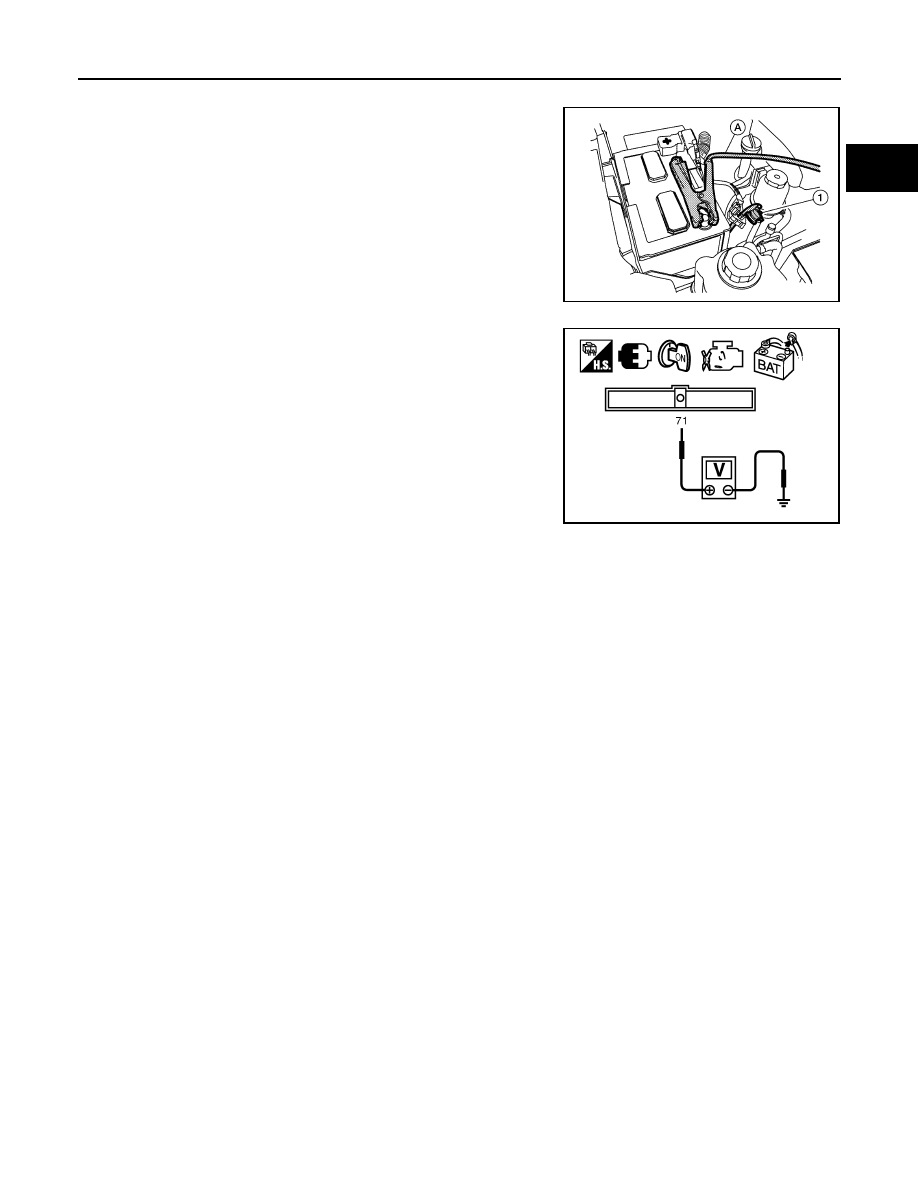
2. Disconnect battery negative cable (1).
3. Install jumper cable (A) between battery negative terminal and

body ground.

4. Turn ignition switch ON.

5. Check voltage between ECM terminal 71 (battery current sensor

signal) and ground.

6. If NG, replace battery negative cable assembly.

BBIA0745E

Voltage: Approximately 2.5V

PBIB2617E

EC-406

< DTC/CIRCUIT DIAGNOSIS >

[VK56DE]

P1564 ASCD STEERING SWITCH

P1564 ASCD STEERING SWITCH

Component Description

INFOID:0000000009886848

ASCD steering switch has variant values of electrical resistance for each button. ECM reads voltage variation

of switch, and determines which button is operated.

Refer to 

EC-28

 for the ASCD function.

On Board Diagnosis Logic

INFOID:0000000009886849

• This self-diagnosis has the one trip detection logic.

• The MIL will not light up for this self-diagnosis.

NOTE:

If DTC P1564 is displayed with DTC P0605, first perform the trouble diagnosis for DTC P0605. Refer to

EC-360

.

DTC Confirmation Procedure

INFOID:0000000009886850

1. If DTC Confirmation Procedure has been previously conducted, always perform the following before con-

ducting the next step.

a. Turn ignition switch OFF and wait at least 10 seconds.
b. Turn ignition switch ON.
c.

Turn ignition switch OFF and wait at least 10 seconds.

2. Turn ignition switch ON.
3. Wait at least 10 seconds.
4. Press MAIN switch for at least 10 seconds, then release it and wait at least 10 seconds.
5. Press CANCEL switch for at least 10 seconds, then release it and wait at least 10 seconds.
6. Press RESUME/ACCELERATE switch for at least 10 seconds, then release it and wait at least 10 sec-

onds.

7. Press SET/COAST switch for at least 10 seconds, then release it and wait at least 10 seconds.
8. Check DTC.
9. If DTC is detected, go to 

EC-406, "Diagnosis Procedure"

.

Diagnosis Procedure

INFOID:0000000009886851

1.

CHECK GROUND CONNECTIONS

1. Turn ignition switch OFF.

2. Loosen and retighten three ground screws on the body.

PBIB2638E

DTC No.

Trouble Diagnosis Name

DTC Detecting Condition

Possible Cause

P1564
1564

ASCD steering switch

• An excessively high voltage signal from the ASCD 

steering switch is sent to ECM.

• ECM detects that input signal from the ASCD steer-

ing switch is out of the specified range.

• ECM detects that the ASCD steering switch is stuck 

ON.

• Harness or connectors

(The switch circuit is open or 
shorted.)

• ASCD steering switch
• Combination switch (spiral ca-

ble)

• ECM

P1564 ASCD STEERING SWITCH

EC-407

< DTC/CIRCUIT DIAGNOSIS >

[VK56DE]

C

D

E

F

G

H

I

J

K

L

M

A

EC

N

P

O

Refer to 

EC-154, "Ground Inspection"

.

OK or NG

OK

>> GO TO 2.

NG

>> Repair or replace ground connections.

2.

CHECK ASCD STEERING SWITCH CIRCUIT

 With CONSULT

1. Turn ignition switch ON.

2. Select “MAIN SW”, “CANCEL SW”, “RESUME/ACC SW” and “SET SW” in “DATA MONITOR” mode with

CONSULT.

3. Check each item indication under the following conditions.

 Without CONSULT

1. Turn ignition switch ON.

2. Check voltage between ECM terminal 99 and ground with press-

ing each button.

OK or NG

OK

>> GO TO 8.

NG

>> GO TO 3.

3.

CHECK ASCD STEERING SWITCH GROUND CIRCUIT FOR OPEN AND SHORT

1. Turn ignition switch OFF.

BBIA0354E

Switch Monitor 

item

Condition

Indication

MAIN switch

MAIN SW

Pressed

ON

Released

OFF

CANCEL switch

CANCEL SW

Pressed

ON

Released

OFF

RESUME/ACCELERATE 
switch

RESUME/ACC SW

Pressed

ON

Released

OFF

SET/COAST switch

SET SW

Pressed

ON 

Released

OFF

Switch

Condition

Voltage [V]

MAIN switch

Pressed

Approx. 0

Released

Approx. 4

CANCEL switch

Pressed

Approx. 1

Released

Approx. 4

RESUME/ACCELERATE 
switch

Pressed Approx. 

3

Released

Approx. 4

SET/COAST switch

Pressed

Approx. 2

Released

Approx. 4

PBIB0311E

EC-408

< DTC/CIRCUIT DIAGNOSIS >

[VK56DE]

P1564 ASCD STEERING SWITCH

2. Disconnect combination switch harness connector M30.

3. Disconnect ECM harness connector.

4. Check harness continuity between combination switch terminal

26 and ECM terminal 67.

Refer to Wiring Diagram.

5. Also check harness for short to ground and short to power.
OK or NG

OK

>> GO TO 5.

NG

>> GO TO 4.

4.

DETECT MALFUNCTIONING PART

Check the following.

• Harness connectors M31, E152

• Harness connectors E5, F14

• Combination switch (spiral cable)

• Harness for open and short between ECM and combination switch

>> Repair open circuit or short to ground or short to power in harness or connectors.

5.

CHECK ASCD STEERING SWITCH INPUT SIGNAL CIRCUIT FOR OPEN AND SHORT

1. Check harness continuity between ECM terminal 99 and combination switch terminal 27.

Refer to Wiring Diagram.

2. Also check harness for short to ground and short to power.
OK or NG

OK

>> GO TO 7.

NG

>> GO TO 6.

6.

DETECT MALFUNCTIONING PART

Check the following.

• Harness connectors M31, E152

• Combination switch (spiral cable)

• Harness for open and short between ECM and combination switch

>> Repair open circuit or short to ground or short to power in harness or connectors.

7.

CHECK ASCD STEERING SWITCH

Refer to 

EC-408, "Component Inspection"

.

OK or NG

OK

>> GO TO 8.

NG

>> Replace ASCD steering switch.

8.

CHECK INTERMITTENT INCIDENT

Refer to 

GI-39, "How to Check Terminal"

 and 

GI-42, "Intermittent Incident"

.

>> INSPECTION END

Component Inspection

INFOID:0000000009886852

ASCD STEERING SWITCH

1. Disconnect combination switch (spiral cable) harness connector M102.

Continuity should exist.

BBIA0362E

Continuity should exist.


Content   ..  274  275  276  277   ..