Nissan Titan. Manual - part 270
P1220 FUEL PUMP CONTROL MODULE (FPCM)
EC-381
< DTC/CIRCUIT DIAGNOSIS >
[VK56DE]
C
D
E
F
G
H
I
J
K
L
M
A
EC
N
P
O
P1220 FUEL PUMP CONTROL MODULE (FPCM)
Description
INFOID:0000000009886815
SYSTEM DESCRIPTION
*: ECM determines the start signal status by the signals of engine speed and battery voltage.
This system controls the fuel pump operation. The amount of fuel flow delivered from the fuel pump is altered
between two flow rates by the FPCM operation. The FPCM determines the voltage supplied to the fuel pump
(and therefore fuel flow) according to the following conditions.
COMPONENT DESCRIPTION
The FPCM adjusts the voltage supplied to the fuel pump to control
the amount of fuel flow. When the FPCM increases the voltage sup-
plied to the fuel pump, the fuel flow is increased. When the FPCM
decreases the voltage, the fuel flow is decreased.
On Board Diagnosis Logic
INFOID:0000000009886816
DTC Confirmation Procedure
INFOID:0000000009886817
CAUTION:
Always drive vehicle at a safe speed.
NOTE:
If DTC Confirmation Procedure has been previously conducted, always perform the following before conduct-
ing the next step.
1. Turn ignition swich OFF and wait at least 10 seconds.
2. Turn ignition swich ON.
3. Turn ignition swich OFF and wait at least 10 seconds.
TESTING CONDITION:
Sensor
Input Signal to ECM
ECM function
Actuator
Crankshaft position sensor (POS)
Camshaft position sensor (PHASE)
Engine speed*
Fuel pump control
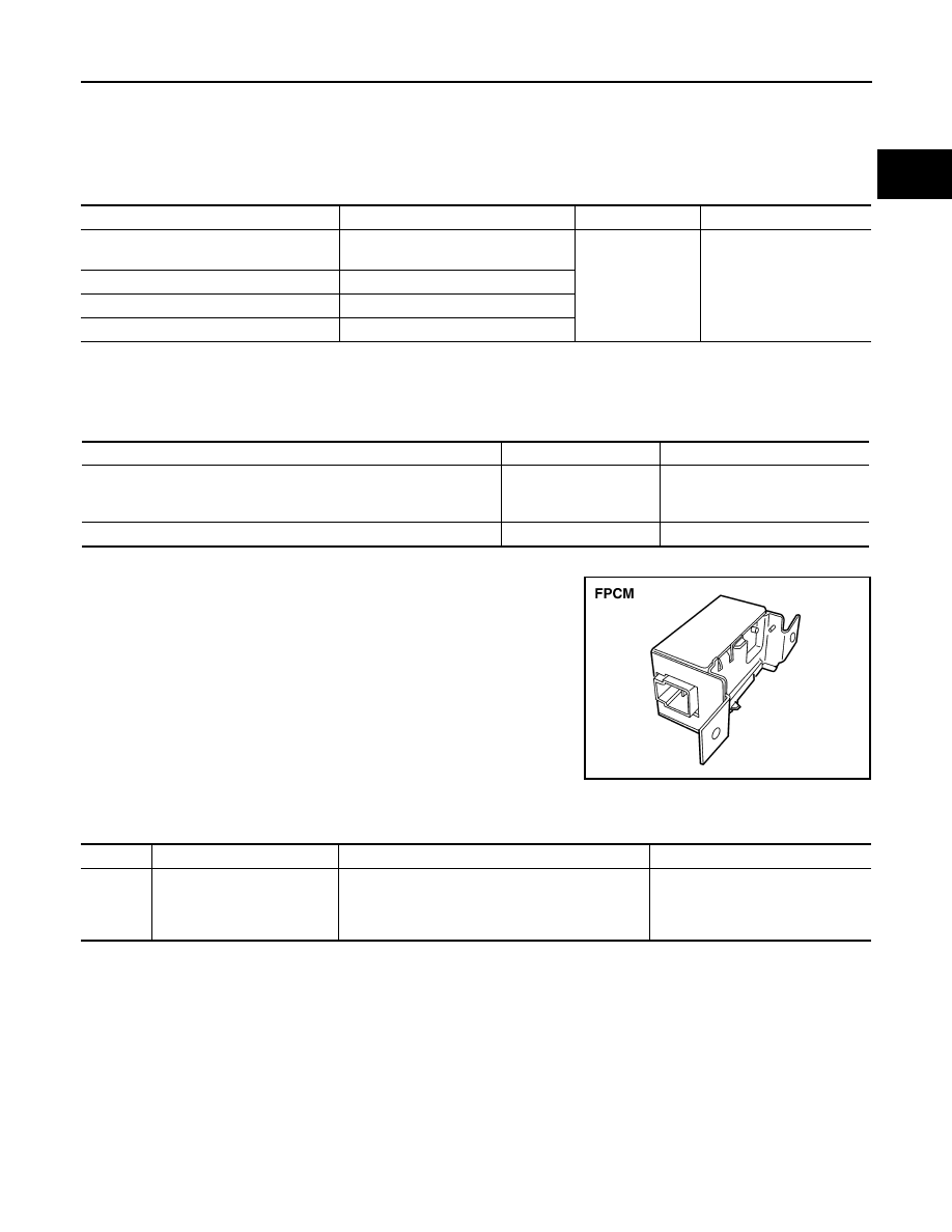
Fuel pump control module
(FPCM)
Mass air flow sensor
Amount of intake air
Engine coolant temperature sensor
Engine coolant temperature
Battery
Battery voltage*
Conditions
Amount of fuel flow
Supplied voltage
• Engine cranking
• Engine coolant temperature is below 10
°C (50°F).
• Engine is running under heavy load and high speed conditions
high
Battery voltage
(11 - 14V)
Except the above
low
Approximately 8V
BBIA0601E
DTC No.
Trouble diagnosis name
DTC detecting condition
Possible cause
P1220
1220
Fuel pump control module
(FPCM)
An improper voltage signal from the FPCM, which is
supplied to a point between the fuel pump and the
dropping resistor, is detected by ECM.
• Harness or connectors
(FPCM circuit is shorted.)
• Dropping resistor
• FPCM