Nissan Titan. Manual - part 267


  Index      Nissan     Nissan Titan (2014 year) - Service and Repair Manual


Search            


Content   ..  265  266  267  268   ..


Nissan Titan. Manual - part 267


P0850 PNP SWITCH

EC-369

< DTC/CIRCUIT DIAGNOSIS >

[VK56DE]

C

D

E

F

G

H

I

J

K

L

M

A

EC

N

P

O

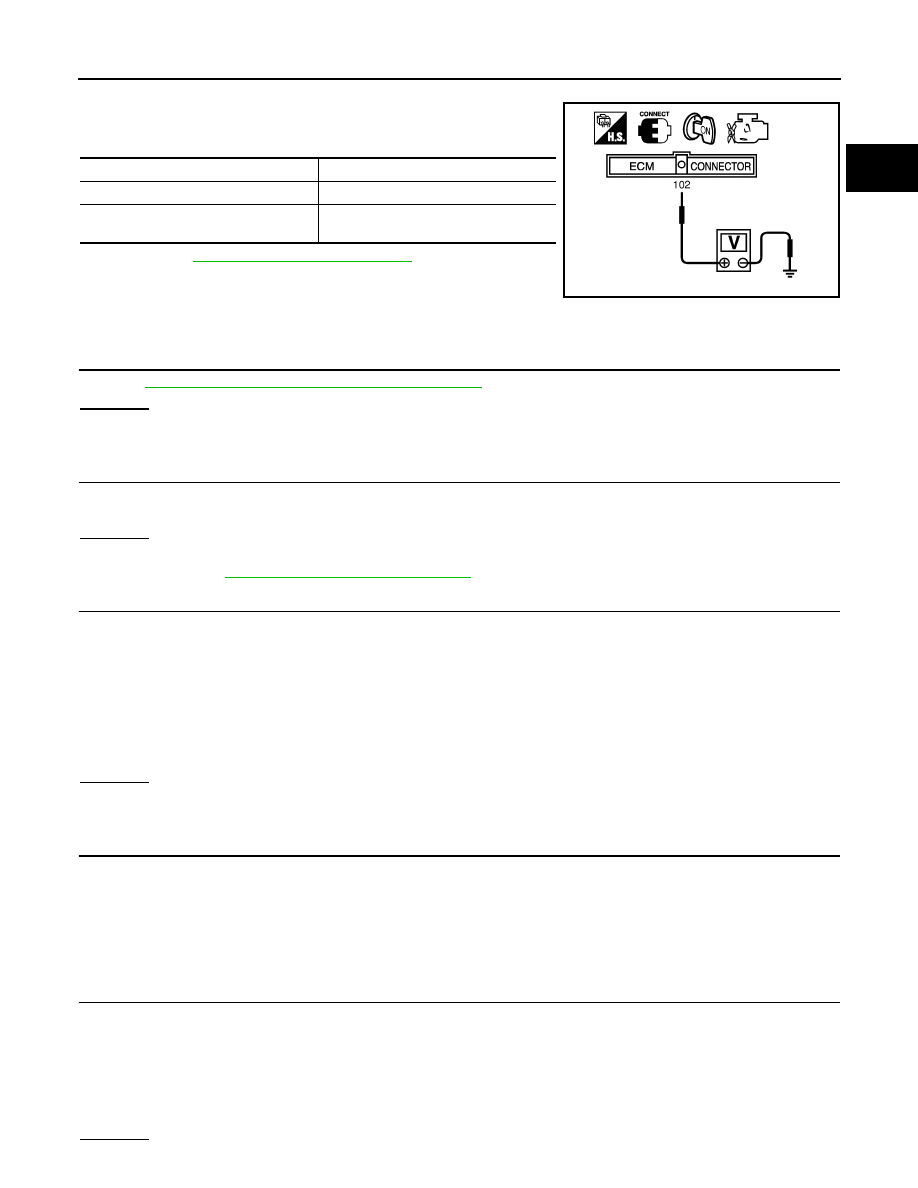
1. Turn ignition switch ON.

2. Check voltage between ECM terminal 102 (PNP signal) and

ground under the following conditions.

3. If NG, go to 

EC-369, "Diagnosis Procedure"

.

Diagnosis Procedure

INFOID:0000000009886796

1.

CHECK DTC WITH TCM

 Refer to 

TM-36, "OBD-II Diagnostic Trouble Code (DTC)"

.

OK or NG

OK

>> GO TO 2.

NG

>> Repair or replace.

2.

CHECK STARTING SYSTEM

Turn ignition switch OFF, then turn it to START.

Does starter motor operate?
Yes or No

Yes

>> GO TO 3.

No

>> Refer to 

STR-19, "Removal and Installation"

.

3.

CHECK PNP INPUT SIGNAL CIRCUIT FOR OPEN AND SHORT-I

1. Turn ignition switch OFF.

2. Disconnect A/T assembly harness connector.

3. Disconnect combination meter harness connector.

4. Check harness continuity between A/T assembly terminal 9 and combination meter terminal 39.

Refer to Wiring Diagram.

5. Also check harness for short to ground and short to power.
OK or NG

OK

>> GO TO 5.

NG

>> GO TO 4.

4.

DETECT MALFUNCTIONING PART

Check the following.

• Harness connectors F14, E5

• Harness connectors E152, M31

• Harness for open or short between A/T assembly and combination meter

>> Repair open circuit or short to ground or short to power in harness or connectors.

5.

CHECK PNP INPUT SIGNAL CIRCUIT FOR OPEN AND SHORT-II

1. Disconnect ECM harness connector.

2. Check harness continuity between ECM terminal 102 and combination meter terminal 40.

Refer to Wiring Diagram.

3. Also check harness for short to ground and short to power.
OK or NG

Condition (Gear position)

Voltage  (V) (Known good data)

P or N position

Approx. 0

Except the above position

BATTERY VOLTAGE

(11 - 14V)

MBIB0043E

Continuity should exist.

Continuity should exist.

EC-370

< DTC/CIRCUIT DIAGNOSIS >

[VK56DE]

P0850 PNP SWITCH

OK

>> GO TO 7.

NG

>> GO TO 6.

6.

 DETECT MALFUNCTIONING PART

Check the following.

• Harness connectors M31, E152

• Harness for open or short between ECM and combination meter

>> Repair open circuit or short to ground or short to power in harness or connectors.

7.

CHECK PNP INPUT SIGNAL CIRCUIT FOR OPEN AND SHORT-III

1. Disconnect TCM harness connector.

2. Check harness continuity between TCM terminal 8 and A/T assembly terminal 9.

Refer to Wiring Diagram.

3. Also check harness for short to ground and short to power.
OK or NG

OK

>> GO TO 8.

NG

>> Repair open circuit or short to ground or short to power in harness or connectors.

8.

CHECK INTERMITTENT INCIDENT

Refer to 

GI-39, "How to Check Terminal"

 and 

GI-42, "Intermittent Incident"

.

OK or NG

OK

>> GO TO 9.

NG

>> Repair or replace.

9.

REPLACE COMBINATION METER FUNCTION

Refer to 

MWI-28, "CONSULT Function (METER/M&A)"

.

>> INSPECTION END

Continuity should exist.

P1140, P1145 IVT CONTROL POSITION SENSOR

EC-371

< DTC/CIRCUIT DIAGNOSIS >

[VK56DE]

C

D

E

F

G

H

I

J

K

L

M

A

EC

N

P

O

P1140, P1145 IVT CONTROL POSITION SENSOR

Component Description

INFOID:0000000009886797

Intake valve timing control position sensors are located in the front of

cylinder heads in both bank 1 and bank 2.

This sensor uses a Hall IC.

The cam position is determined by the intake camshaft sprocket con-

cave (in four places). The ECM provides feedback to the intake valve

timing control for appropriate target valve open-close timing accord-

ing to drive conditions based on detected cam position.

On Board Diagnosis Logic

INFOID:0000000009886798

DTC Confirmation Procedure

INFOID:0000000009886799

1. If DTC Confirmation Procedure has been previously conducted, always perform the following before con-

ducting the next step.

a. Turn ignition switch OFF and wait at least 10 seconds.
b. Turn ignition switch ON.
c. Turn ignition switch OFF and wait at least 10 seconds.
2. Turn ignition switch ON.
3. Select “DATA MONITOR” mode with CONSULT.
4. Maintain the following conditions for at least 10 seconds.

5. Check 1st trip DTC.
6. If 1st trip DTC is detected, go to 

EC-371, "Diagnosis Procedure"

.

Diagnosis Procedure

INFOID:0000000009886800

1.

CHECK GROUND CONNECTIONS

1. Turn ignition switch OFF.

2. Loosen and retighten three ground screws on the body.

SEF359Z

DTC No.

Trouble diagnosis name

DTC detecting condition

Possible cause

P1140
1140
(Bank 1)

Intake valve timing control 
position sensor circuit

An excessively high or low voltage from the 
sensor is sent to ECM.

• Harness or connectors

(Intake valve timing control position 
sensor circuit is open or shorted)

• Intake valve timing control position 

sensor

• Crankshaft position sensor (POS)
• Camshaft position sensor (PHASE)
• Accumulation of debris to the signal 

pick-up portion of the camshaft sprock-
et

P1145
1145
(Bank 2)

ENG SPEED

More than idle speed

Selector lever

P or N position

EC-372

< DTC/CIRCUIT DIAGNOSIS >

[VK56DE]

P1140, P1145 IVT CONTROL POSITION SENSOR

Refer to 

EC-154, "Ground Inspection"

.

OK or NG

OK

>> GO TO 2.

NG

>> Repair or replace ground connections.

2.

CHECK INTAKE VALVE TIMING CONTROL POSITION SENSOR POWER SUPPLY CIRCUIT

1. Disconnect intake valve timing control position sensor harness connector.

2. Turn ignition switch ON.

3. Check voltage between intake valve timing control position sen-

sor terminal 3 and ground with CONSULT or tester.

OK or NG

OK

>> GO TO 4.

NG

>> GO TO 3.

3.

DETECT MALFUNCTIONING PART

Check the following.

• Harness connectors E2, F32

• Harness for open or short between intake valve timing control position sensor and IPDM E/R

• Harness for open or short between intake valve timing control position sensor and ECM

>> Repair open circuit or short to ground or short to power in harness or connectors.

4.

CHECK INTAKE VALVE TIMING CONTROL POSITION SENSOR GROUND CIRCUIT FOR OPEN AND

SHORT
1. Turn ignition switch OFF.

2. Check harness continuity between intake valve timing control position sensor terminal 1 and ground.

Refer to Wiring Diagram.

BBIA0354E

1.

Intake valve timing control position 
sensor (bank 2)

2.

Intake valve timing control solenoid 
valve (bank 2)

3.

Drive belt

4.

Radiator hose

5.

Intake valve timing control solenoid 
valve (bank 1)

6.

Intake valve timing control position 
sensor (bank 1)

Voltage: Battery voltage

BBIA0771E

PBIB2613E


Content   ..  265  266  267  268   ..