Nissan Titan. Manual - part 242


  Index      Nissan     Nissan Titan (2014 year) - Service and Repair Manual


Search            


Content   ..  240  241  242  243   ..


Nissan Titan. Manual - part 242


P0327, P0328, P0332, P0333 KS

EC-269

< DTC/CIRCUIT DIAGNOSIS >

[VK56DE]

C

D

E

F

G

H

I

J

K

L

M

A

EC

N

P

O

P0327, P0328, P0332, P0333 KS

Component Description

INFOID:0000000009886673

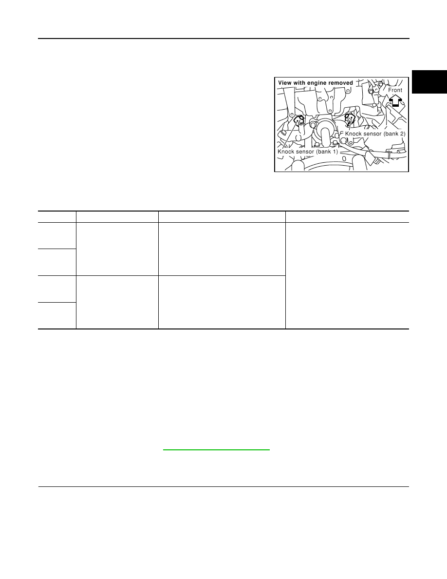
The knock sensor is attached to the cylinder block. It senses engine

knocking using a piezoelectric element. A knocking vibration from

the cylinder block is sensed as vibrational pressure. This pressure is

converted into a voltage signal and sent to the ECM.

On Board Diagnosis Logic

INFOID:0000000009886674

The MIL will not light up for these self-diagnoses.

DTC Confirmation Procedure

INFOID:0000000009886675

NOTE:

If DTC Confirmation Procedure has been previously conducted, always perform the following before conduct-

ing the next step. 
1. Turn ignition swich OFF and wait at least 10 seconds.
2. Turn ignition swich ON.
3. Turn ignition swich OFF and wait at least 10 seconds.
TESTING CONDITION:

Before performing the following procedure, confirm that battery voltage is more than 10V at idle.

1. Start engine and run it for at least 5 seconds at idle speed.

2. Check 1st trip DTC.

3. If 1st trip DTC is detected, go to 

EC-269, "Diagnosis Procedure"

.

Diagnosis Procedure

INFOID:0000000009886676

1.

CHECK KNOCK SENSOR INPUT SIGNAL CIRCUIT FOR OPEN AND SHORT-I

1. Turn ignition switch OFF.

2. Disconnect ECM harness connector.

3. Check resistance between ECM terminals 15, 36 and ground. Refer to Wiring Diagram.

NOTE:

It is necessary to use an ohmmeter which can measure more than 10 M

.

PBIB0021E

DTC No.

Trouble diagnosis name

DTC detecting condition

Possible cause

P0327
0327
(bank 1)

Knock sensor circuit low in-
put

An excessively low voltage from the sensor 
is sent to ECM.

• Harness or connectors

(The sensor circuit is open or shorted.)

• Knock sensor

P0332
0332
(bank 2)

P0328
0328
(bank 1)

Knock sensor circuit high in-
put

An excessively high voltage from the sensor 
is sent to ECM.

P0333
0333
(bank 2)

Resistance: Approximately 532 - 588 k

 [at 20°C (68°F)]

EC-270

< DTC/CIRCUIT DIAGNOSIS >

[VK56DE]

P0327, P0328, P0332, P0333 KS

4. Also check harness for short to ground and short to power.
OK or NG

OK

>> GO TO 5.

NG

>> GO TO 2.

2.

CHECK KNOCK SENSOR INPUT SIGNAL CIRCUIT FOR OPEN AND SHORT-II

1. Disconnect knock sensor harness connector.

2. Check harness continuity between ECM terminal 15 and knock

sensor (bank1) terminal 1, ECM terminal 36 and knock sensor

(bank 2) terminal 1. 

Refer to Wiring Diagram.

3. Also check harness for short to ground and short to power.
OK or NG

OK

>> GO TO 4.

NG

>> GO TO 3.

3.

DETECT MALFUNCTIONING PART

Check the following.

• Harness connectors F26, F201

• Harness for open or short between ECM and knock sensor

>> Repair open circuit or short to ground or short to power in harness or connectors.

4.

CHECK KNOCK SENSOR

Refer to 

EC-271, "Component Inspection"

.

OK or NG

OK

>> GO TO 5.

NG

>> Replace malfunctioning knock sensor.

5.

CHECK GROUND CONNECTIONS

Loosen and retighten three ground screws on the body.

Refer to 

EC-154, "Ground Inspection"

.

OK or NG

OK

>> GO TO 6.

NG

>> Repair or replace ground connections.

6.

CHECK KNOCK SENSOR SHIELD CIRCUIT FOR OPEN AND SHORT

1. Disconnect knock sensor harness connector.

2. Check harness continuity between knock sensor terminal 2 and ground. Refer to Wiring Diagram.

3. Also check harness for short to power.
OK or NG

OK

>> GO TO 8.

NG

>> GO TO 7.

Continuity should exist.

PBIB0021E

BBIA0354E

Continuity should exist.

P0327, P0328, P0332, P0333 KS

EC-271

< DTC/CIRCUIT DIAGNOSIS >

[VK56DE]

C

D

E

F

G

H

I

J

K

L

M

A

EC

N

P

O

7.

DETECT MALFUNCTIONING PART

Check the following.

• Harness connectors F26, F201

• Harness connectors F14, E5

• Harness for open or short between knock sensor terminal 2 and ground

>> Repair open circuit or short power in harness or connectors.

8.

CHECK INTERMITTENT INCIDENT

Refer to 

GI-39, "How to Check Terminal"

 and 

GI-42, "Intermittent Incident"

.

>> INSPECTION END

Component Inspection

INFOID:0000000009886677

KNOCK SENSOR

Check resistance between knock sensor terminal 1 and ground.

NOTE:

It is necessary to use an ohmmeter which can measure more

than 10 M

.

CAUTION:

Do not use any knock sensors that have been dropped or phys-

ically damaged. Use only new ones.

Resistance: Approximately 532 - 588 k

 [at 20°C (68°F)]

SEF227W

EC-272

< DTC/CIRCUIT DIAGNOSIS >

[VK56DE]

P0335 CKP SENSOR (POS)

P0335 CKP SENSOR (POS)

Component Description

INFOID:0000000009886678

The crankshaft position sensor (POS) is located on the A/T assem-

bly facing the gear teeth (cogs) of the signal plate. It detects the fluc-

tuation of the engine revolution.

The sensor consists of a permanent magnet and Hall IC.

When the engine is running, the high and low parts of the teeth

cause the gap with the sensor to change.

The changing gap causes the magnetic field near the sensor to

change.

Due to the changing magnetic field, the voltage from the sensor

changes. 

The ECM receives the voltage signal and detects the fluctuation of

the engine revolution.

ECM receives the signals as shown in the figure.

On Board Diagnosis Logic

INFOID:0000000009886679

DTC Confirmation Procedure

INFOID:0000000009886680

NOTE:

If DTC Confirmation Procedure has been previously conducted, always perform the following before conduct-

ing the next step. 
1. Turn ignition swich OFF and wait at least 10 seconds.
2. Turn ignition swich ON.
3. Turn ignition swich OFF and wait at least 10 seconds.
TESTING CONDITION:

Before performing the following procedure, confirm that battery voltage is more than 10.5V with igni-

tion switch ON.

1.  Crank engine for at least 2 seconds and run it for at least 5 seconds at idle speed.

2.  Check 1st DTC.

3. If 1st trip DTC is detected, go to 

EC-272, "Diagnosis Procedure"

.

Diagnosis Procedure

INFOID:0000000009886681

1.

CHECK GROUND CONNECTIONS

PBIB0562E

PBIB3459E

DTC No.

Trouble diagnosis name

DTC detecting condition

Possible cause

P0335
0335

Crankshaft position sen-
sor (POS) circuit

• The crankshaft position sensor (POS) signal 

is not detected by the ECM during the first 
few seconds of engine cranking.

• The proper pulse signal from the crankshaft 

position sensor (POS) is not sent to ECM 
while the engine is running.

• The crankshaft position sensor (POS) signal 

is not in the normal pattern during engine run-
ning.

• Harness or connectors

(The sensor circuit is open or shorted)

• Crankshaft position sensor (POS)
• Signal plate


Content   ..  240  241  242  243   ..