Nissan Titan. Manual - part 226


  Index      Nissan     Nissan Titan (2014 year) - Service and Repair Manual


Search            


Content   ..  224  225  226  227   ..


Nissan Titan. Manual - part 226


P0130, P0150 A/F SENSOR 1

EC-205

< DTC/CIRCUIT DIAGNOSIS >

[VK56DE]

C

D

E

F

G

H

I

J

K

L

M

A

EC

N

P

O

P0130, P0150 A/F SENSOR 1

Component Description

INFOID:0000000009886614

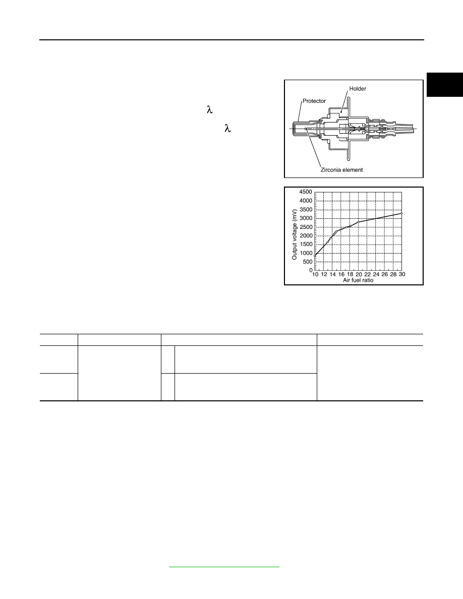
The air fuel ratio (A/F) sensor 1 is a planar one-cell limit current sen-

sor. The sensor element of the A/F sensor 1 is composed an elec-

trode layer, which transports ions. It has a heater in the element.
The sensor is capable of precise measurement   = 1, but also in the

lean and rich range. Together with its control electronics, the sensor
outputs a clear, continuous signal throughout a wide   range.

The exhaust gas components diffuse through the diffusion layer at

the sensor cell. An electrode layer is applied voltage, and this current

relative oxygen density in lean. Also this current relative hydrocar-

bon density in rich.

Therefore, the A/F sensor 1 is able to indicate air fuel ratio by this

electrode layer of current. In addition, a heater is integrated in the

sensor to ensure the required operating temperature of about 800

°C

(1,472

°F).

On Board Diagnosis Logic

INFOID:0000000009886615

To judge the malfunction, the diagnosis checks that the A/F signal computed by ECM from the A/F sensor 1

signal fluctuates according to fuel feedback control.

DTC Confirmation Procedure

INFOID:0000000009886616

Perform PROCEDURE FOR MALFUNCTION A first.

If the DTC cannot be confirmed, perform PROCEDURE FOR MALFUNCTION B.

NOTE:

If DTC Confirmation Procedure has been previously conducted, always perform the following before conduct-

ing the next step. 
1. Turn ignition swich OFF and wait at least 10 seconds.
2. Turn ignition swich ON.
3. Turn ignition swich OFF and wait at least 10 seconds.
TESTING CONDITION:

Before performing the following procedure, confirm that battery voltage is more than 11V at idle.

PROCEDURE FOR MALFUNCTION A

1. Start engine and warm it up to normal operating temperature.

2. Let engine idle for 2 minutes.

3. Check 1st trip DTC.

4. If 1st trip DTC is detected, go to 

EC-206, "Diagnosis Procedure"

.

PBIB3353E

JPBIA5446GB

DTC No.

Trouble diagnosis name

DTC detecting condition

Possible Cause

P0130
0130
(Bank 1)

Air fuel ratio (A/F) sensor 1 
circuit

A)

The A/F signal computed by ECM from the A/F 
sensor 1 signal is constantly in the range other 
than approx. 2.2V.

• Harness or connectors

(The A/F sensor 1 circuit is open 
or shorted.)

• Air fuel ratio (A/F) sensor 1

P0150
0150
(Bank 2)

B)

The A/F signal computed by ECM from the A/F 
sensor 1 signal is constantly approx. 2.2V.

EC-206

< DTC/CIRCUIT DIAGNOSIS >

[VK56DE]

P0130, P0150 A/F SENSOR 1

PROCEDURE FOR MALFUNCTION B

CAUTION:

Always drive vehicle at a safe speed.

 With CONSULT

1. Start engine and warm it up to normal operating temperature.

2. Select “A/F SEN1 (B1)” or “A/F SEN1 (B2)” in “DATA MONITOR” mode with CONSULT.

3. Check “A/F SEN1 (B1)” or “A/F SEN1 (B2)” indication.

If the indication is constantly approx. 2.2V and does not fluctuates, go to 

EC-206, "Diagnosis Procedure"

.

If the indication fluctuates around 2.2V, go to next step.

4. Select “A/F SEN1 (B1) P1276” (for DTC P0130) or “A/F SEN1 (B2) P1286” (for DTC P0150) of “A/F

SEN1” in “DTC WORK SUPPORT” mode with CONSULT.

5. Touch “START”.

6. When the following conditions are met, “TESTING” will be displayed on the CONSULT screen.

If “TESTING” is not displayed after 20 seconds, retry from step 2.

7. Release accelerator pedal fully.

NOTE:

Never apply brake during releasing the accelerator pedal.

8. Make sure that “TESTING” changes to “COMPLETED”.

If “TESTING” changed to “OUT OF CONDITION”, retry from step 6.

9. Make sure that “OK” is displayed after touching “SELF-DIAG RESULT”. 

If “NG” is displayed, go to 

EC-206, "Diagnosis Procedure"

.

Overall Function Check

INFOID:0000000009886617

PROCEDURE FOR MALFUNCTION B

Use this procedure to check the overall function of the A/F sensor 1 circuit. During this check, a 1st trip DTC

might not be confirmed.

 With GST

1. Start engine and warm it up to normal operating temperature.

2. Drive the vehicle at a speed of 80 km/h (50 MPH) for a few minutes in the suitable gear position.

3. Set shift lever to D position, then release the accelerator pedal fully until the vehicle speed decreases to

50 km/h (30 MPH).

NOTE:

Never apply brake during releasing the accelerator pedal.

4. Repeat steps 2 and 3 for five times.

5. Stop the vehicle and turn ignition switch OFF.

6. Wait at least 10 seconds and restart engine.

7. Repeat steps 2 and 3 for five times.

8. Stop the vehicle and connect GST to the vehicle.

9. Make sure that no 1st trip DTC is displayed.

If the 1st trip DTC is displayed, go to 

EC-206, "Diagnosis Procedure"

.

Diagnosis Procedure

INFOID:0000000009886618

1.

CHECK GROUND CONNECTIONS

1. Turn ignition switch OFF.

2. Loosen and retighten three ground screws on the body.

ENG SPEED

850 - 3,200 rpm

VHCL SPEED SE

More than 64 km/h (40 MPH)

B/FUEL SCHDL

1.0 - 8.0 msec

Shift lever

D position

P0130, P0150 A/F SENSOR 1

EC-207

< DTC/CIRCUIT DIAGNOSIS >

[VK56DE]

C

D

E

F

G

H

I

J

K

L

M

A

EC

N

P

O

Refer to 

EC-154, "Ground Inspection"

.

OK or NG

OK

>> GO TO 2.

NG

>> Repair or replace ground connections.

2.

CHECK AIR FUEL RATIO (A/F) SENSOR 1 POWER SUPPLY CIRCUIT

1. Disconnect A/F sensor 1 harness connector.

2. Turn ignition switch ON.

3. Check voltage between A/F sensor 1 terminal 4 and ground with

CONSULT or tester.

OK or NG

OK

>> GO TO 4.

NG

>> GO TO 3.

3.

DETECT MALFUNCTIONING PART

Check the following.

• Harness connectors E5, F14

• IPDM E/R harness connector E119

• 15A fuse

• Harness for open or short between A/F sensor 1 and fuse

>> Repair or replace harness or connectors.

4.

CHECK A/F SENSOR 1 INPUT SIGNAL CIRCUIT FOR OPEN AND SHORT

1. Turn ignition switch OFF.

2. Disconnect ECM harness connector.

3. Check harness continuity between the following terminals. Refer to Wiring Diagram.

BBIA0354E

Voltage: Battery voltage

BBIA0376E

JSBIA3095GB

A/F sensor 1 terminal

ECM terminal

Bank1

1

35

2

56

EC-208

< DTC/CIRCUIT DIAGNOSIS >

[VK56DE]

P0130, P0150 A/F SENSOR 1

4. Check harness continuity between the following terminals and ground.

Refer to Wiring Diagram.

5. Also check harness for short to power.
OK or NG

OK

>> GO TO 5.

NG

>> Repair open circuit or short to ground or short to power in harness or connectors.

5.

CHECK INTERMITTENT INCIDENT

Perform 

GI-39, "How to Check Terminal"

 and 

GI-42, "Intermittent Incident"

.

OK or NG

OK

>> GO TO 6.

NG

>> Repair or replace.

6.

REPLACE AIR FUEL RATIO (A/F) SENSOR 1

Replace malfunctioning air fuel ratio (A/F) sensor 1.

CAUTION:

• Discard any A/F sensor which has been dropped from a height of more than 0.5 m (19.7 in) onto a

hard surface such as a concrete floor; use a new one.

• Before installing new A/F sensor, clean exhaust system threads using Oxygen Sensor Thread

Cleaner tool J-43897-18 or J-43897-12 and approved anti-seize lubricant.

>> INSPECTION END

Bank 2

1

16

2

75

Continuity should exist.

Bank 1

Bank 2

A/F sensor 1 terminal

ECM terminal

A/F sensor 1 terminal

ECM terminal

1

35

1

16

2

56

2

75

Continuity should not exist.


Content   ..  224  225  226  227   ..