Nissan Titan. Manual - part 186
DIAGNOSIS SYSTEM (ECM)
EC-45
< SYSTEM DESCRIPTION >
[VK56DE]
C
D
E
F
G
H
I
J
K
L
M
A
EC
N
P
O
If, during the state emissions inspection, the SRT indicates “CMPLT” for all test items, the inspector will con-
tinue with the emissions test. However, if the SRT indicates “INCMP” for one or more of the SRT items the
vehicle is returned to the customer untested.
NOTE:
If permanent DTC is stored or MIL illuminates during the state emissions inspection, the vehicle is also
returned to the customer untested even though the SRT indicates “CMPLT” for all test items. Therefore, it is
important to check SRT (“CMPLT”), DTC (No DTCs) and permanent DTC (NO permanent DTCs) before the
inspection.
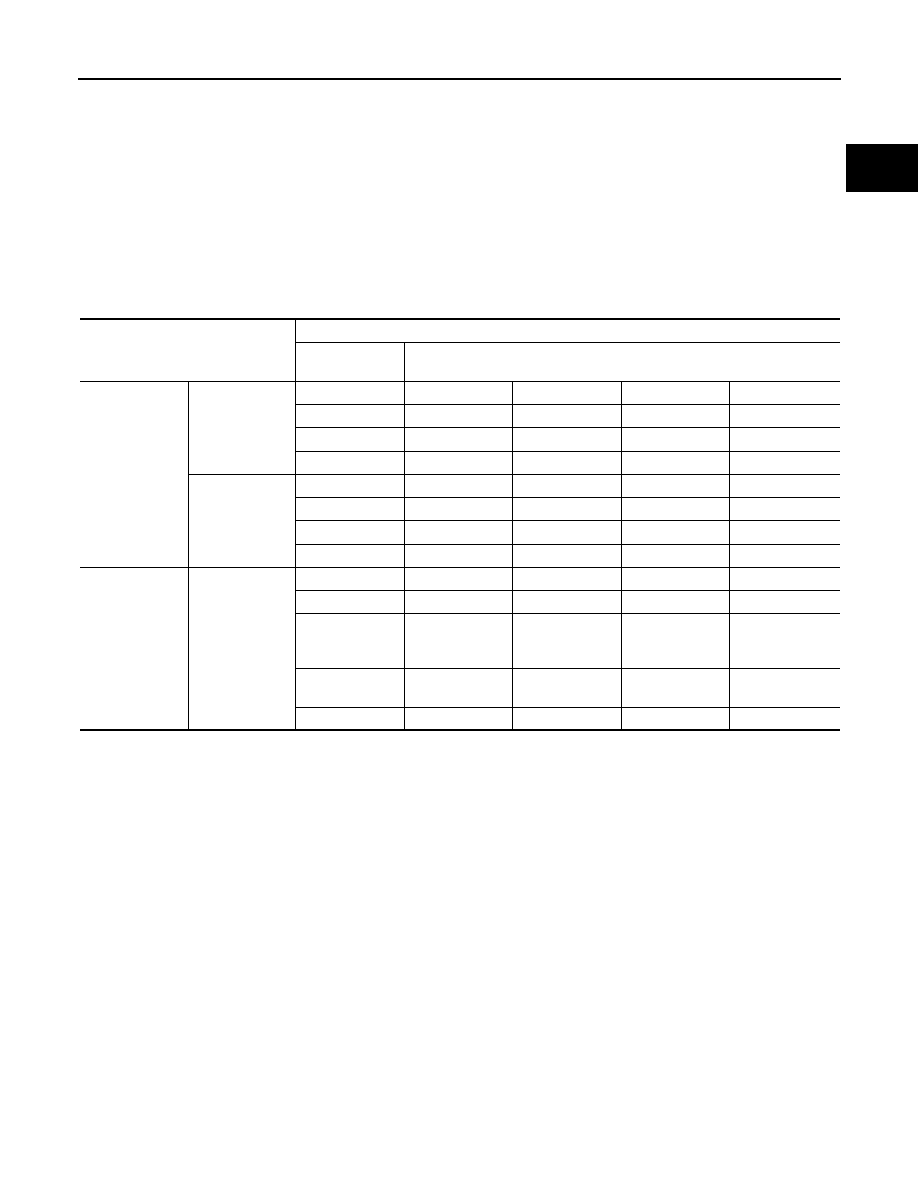
SRT SET TIMING
SRT is set as “CMPLT” after self-diagnosis has been performed one or more times. Completion of SRT is
done regardless of whether the result is OK or NG. The set timing is different between OK and NG results and
is shown in the table below.
OK: Self-diagnosis is carried out and the result is OK.
NG: Self-diagnosis is carried out and the result is NG.
—: Self-diagnosis is not carried out.
When all SRT related self-diagnoses show OK results in a single cycle (Ignition OFF-ON-OFF), the SRT will
indicate “CMPLT”.
→ Case 1 above
When all SRT related self-diagnoses show OK results through several different cycles, the SRT will indicate
“CMPLT” at the time the respective self-diagnoses have at least one OK result.
→ Case 2 above
If one or more SRT related self-diagnoses show NG results in 2 consecutive cycles, the SRT will also indicate
“CMPLT”.
→ Case 3 above
The table above shows that the minimum number of cycles for setting SRT as “INCMP” is the number one (1)
for each self-diagnosis (Case 1 & 2) or the number two (2) for one of self-diagnoses (Case 3). However, in
preparation for the state emissions inspection, it is unnecessary for each self-diagnosis to be executed twice
(Case 3) for the following reasons:
• The SRT will indicate “CMPLT” at the time the respective self-diagnoses have one (1) OK result.
• The emissions inspection requires “CMPLT” of the SRT only with OK self-diagnosis results.
• During SRT driving pattern, the 1st trip DTC (NG) is detected prior to “CMPLT” of SRT and the self-diagnosis
memory must be erased from the ECM after repair.
• If the 1st trip DTC is erased, all the SRT will indicate “INCMP”.
NOTE:
SRT can be set as “CMPLT” together with the DTC(s). Therefore, DTC check must always be carried out
prior to the state emission inspection even though the SRT indicates “CMPLT”.
Self-diagnosis result
Example
Diagnosis
Ignition cycle
← ON → OFF ← ON → OFF ← ON → OFF ← ON →
All OK
Case 1
P0400
OK (1)
— (1)
OK (2)
— (2)
P0402
OK (1)
— (1)
— (1)
OK (2)
P1402
OK (1)
OK (2)
— (2)
— (2)
SRT of EGR
“CMPLT”
“CMPLT”
“CMPLT”
“CMPLT”
Case 2
P0400
OK (1)
— (1)
— (1)
— (1)
P0402
— (0)
— (0)
OK (1)
— (1)
P1402
OK (1)
OK (2)
— (2)
— (2)
SRT of EGR
“INCMP”
“INCMP”
“CMPLT”
“CMPLT”
NG exists
Case 3
P0400
OK
OK
—
—
P0402
—
—
—
—
P1402
NG
—
NG
NG
(Consecutive
NG)
(1st trip)
DTC
1st trip DTC
—
1st trip DTC
DTC
(= MIL ON)
SRT of EGR
“INCMP”
“INCMP”
“INCMP”
“CMPLT”