Nissan Titan. Manual - part 180
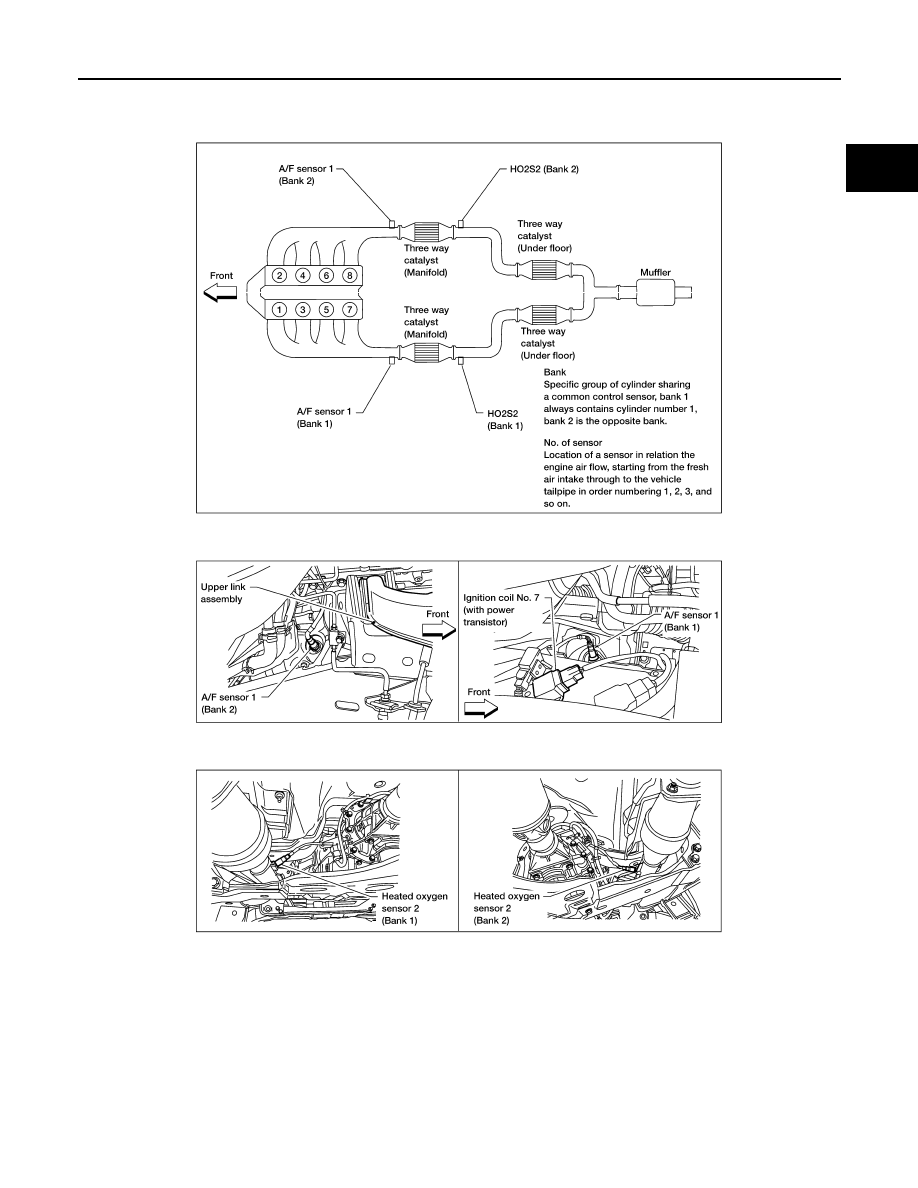
ENGINE CONTROL SYSTEM
EC-21
< SYSTEM DESCRIPTION >
[VK56DE]
C
D
E
F
G
H
I
J
K
L
M
A
EC
N
P
O
BBIA0384E
|
|
|
ENGINE CONTROL SYSTEM EC-21 < SYSTEM DESCRIPTION > [VK56DE] C D E F G H I J K L M A EC N P O BBIA0384E |