Nissan Titan. Manual - part 151


  Index      Nissan     Nissan Titan (2014 year) - Service and Repair Manual


Search            


Content   ..  149  150  151  152   ..


Nissan Titan. Manual - part 151


DLN-176

< UNIT DISASSEMBLY AND ASSEMBLY >

[FRONT FINAL DRIVE: M205]

FRONT FINAL DRIVE

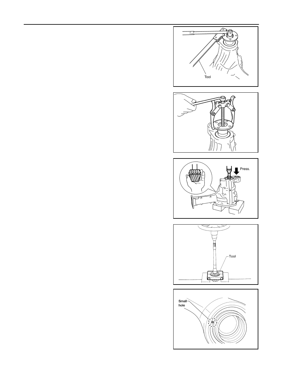
2. Remove the drive pinion lock nut using suitable tool.
3. Put matching marks on the companion flange and drive pinion

using paint.

CAUTION:

Use paint to make the matching marks. Do not damage the

companion flange or drive pinion.

4. Remove the companion flange using suitable tool.

5. Press the drive pinion assembly (with rear inner bearing race

and collapsible spacer) out of the gear carrier.

CAUTION:

Do not drop drive pinion assembly.

6. Remove the drive pinion rear bearing inner race and drive pinion

height adjusting washer using Tool.

7. Place a small hole in the front oil seal case using suitable tool.

PDIA0702E

PDIA0703E

SDIA2234E

Tool number

: ST30021000 ( — )

S-PD179

LDIA0129E

FRONT FINAL DRIVE

DLN-177

< UNIT DISASSEMBLY AND ASSEMBLY >

[FRONT FINAL DRIVE: M205]

C

E

F

G

H

I

J

K

L

M

A

B

DLN

N

O

P

8. Remove the front oil seal using suitable tool as shown.

9. Remove the drive pinion front bearing inner race.
10. Remove the drive pinion front bearing outer race using Tool as

shown. Locate the driver on the back edge of the drive pinion

front bearing outer race, then drive the drive pinion front bearing

outer race out.

CAUTION:

Do not damage gear carrier.

11. Remove the drive pinion rear bearing outer race using Tool as

shown. Locate the driver on the back edge of the drive pinion

rear bearing outer race, then drive the drive pinion rear bearing

outer race out.

CAUTION:

Do not damage gear carrier.

INSPECTION AFTER DISASSEMBLY

Clean the disassembled parts. Then inspect the parts for wear or damage. If wear or damage are found, follow

the measures below.

Drive Pinion and Drive Gear

• If the drive pinion and drive gear teeth do not mesh or line-up correctly, determine the cause and adjust,

repair, or replace as necessary.

• If the drive pinion or drive gear are worn, cracked, damaged, pitted or chipped (by friction) noticeably,

replace with new drive pinion and drive gear.

• Drive pinion and drive gear are supplied in matched sets only. Matching numbers on both drive pinion and

drive gear are etched for verification. If a new drive pinion and drive gear set are being used, verify the num-

bers of each drive pinion and drive gear before proceeding with assembly.

Bearing

• If bearings are chipped (by friction), pitted, worn, rusted, scratched, or unusual noise is coming from bearing,

replace with new bearing assembly (as a new set).

• Bearing must be replaced with a new one whenever disassembled.

Side Gear and Pinion Mate Gear

• If any cracks or damage are found on the surface of the teeth, replace with new one.

• If any worn or chipped marks are found on the side of the side gear and pinion mate gear which contact the

thrust washer, replace with new one.

• Replace both side gear and pinion mate gear as a set when replacing side gear or pinion mate gear.

LDIA0130E

Tool number

(A): — (C-4171)
(B): — (D-103)

LDIA0131E

Tool number

(A): — (C-4171)
(B): — (C-4307)

LDIA0132E

DLN-178

< UNIT DISASSEMBLY AND ASSEMBLY >

[FRONT FINAL DRIVE: M205]

FRONT FINAL DRIVE

Side Gear Thrust Washer and Pinion Mate Thrust Washer

• If any chips (by friction), damage, or unusual wear are found, replace with new one.

Gear Carrier

• If any wear or cracks are found on the contact sides of gear carrier, replace with new one.

Companion Flange

• If any chips (about 0.1mm, 0.004 in) or other damage on the companion flange surface which contacts the

front oil seal lips are found, replace with new one.

ADJUSTING AND SELECTING WASHERS

Side Gear Back Clearance

• Assemble the differential parts if they are disassembled.
1. Place the differential case straight up so that the side gear to be

measured is upward.

2. Using feeler gauges, measure the clearance between the side

gear back and differential case at three different points, while

rotating the side gear. Average the three readings to calculate

the clearance. (Measure the clearance of the other side as well.)

• If the side gear back clearance is outside of the specification,

use a thicker or thinner side gear thrust washer to adjust.

Refer to 

DLN-185, "Inspection and Adjustment"

.

CAUTION:

• Insert feeler gauges with the same thickness on both

sides to prevent side gear from tilting.

• Each gear should rotate smoothly without excessive

resistance during differential motion.

• Select a side gear thrust washer for right and left individually.

NOTE:

Side gear back clearance is clearance between side gear and differential case for adjusting side gear

backlash.

Drive Pinion Height

PDIA0460E

Side gear back clearance: Refer to 

DLN-185, "Inspec-

tion and Adjustment"

If the side gear back clearance is greater than 
specification:

Use a thicker side gear thrust washer.

If the side gear back clearance is less than spec-
ification:

Use a thinner side gear thrust washer.

PDIA0576E

FRONT FINAL DRIVE

DLN-179

< UNIT DISASSEMBLY AND ASSEMBLY >

[FRONT FINAL DRIVE: M205]

C

E

F

G

H

I

J

K

L

M

A

B

DLN

N

O

P

• Drive gear and drive pinion are supplied in matched sets only.

Matching numbers on both drive pinion and drive gear are etched

for verification. If a new gear set is being used, verify the numbers

of each drive pinion and drive gear before proceeding with assem-

bly.

• The mounting distance from the centerline of the drive gear to the back face of the drive pinion for the M205

final drive assembly is 103.5 mm (4.0748 inches).

On the button end of each drive pinion, there is etched a plus (+) number, a minus (-) number, or a zero (0),

which indicates the best running position for each particular gear set. This dimension is controlled by a

selective drive pinion height adjusting washer between the drive pinion rear bearing inner race and drive pin-

ion.

For example: If a drive pinion is etched m+8 (+3), it would require 0.08 mm (0.003 inch) less drive pinion

height adjusting washer than a drive pinion etched “0”. This means decreasing drive pinion height adjusting

washer thickness; increases the mounting distance of the drive pinion to 103.6 mm (4.0787 inches). If a

drive pinion is etched m-8 (-3), it would require adding 0.08mm (0.003 inch) more to the drive pinion height

adjusting washer than would be required if the drive pinion were etched “0”. By adding 0.08 mm (0.003 inch),

the mounting distance of the drive pinion was decreased to 103.4 mm (4.0709 inches) which is just what a

m-8 (-3) etching indicated.      

• To change the drive pinion height, use different drive pinion height adjusting washers which come in different

thickness.

• Use the following tables as a guide for selecting the correct drive pinion height adjusting washer thickness to

add or subtract from the old drive pinion height adjusting washer.

ASSEMBLY

Drive Pinion Assembly

SDIA2241E

OLD DRIVE 

PINION 

MARKING

NEW DRIVE PINION MARKING mm (in)

-10 (-4)

-8 (-3)

-5 (-2)

-3 (-1)

0 (0)

+3 (+1)

+5 (+2)

+8 (+3)

+10 (+4)

+10 (+4)

+0.20

(+0.008)

+0.18

(+0.007) 

+0.15

(+0.006)

+0.13

(+0.005)

+0.10

(+0.004)

+0.08

(+0.003)

+0.05

(+0.002)

+0.02

(+0.001)

0

(0)

+8 (+3)

+0.18

(+0.007)

+0.15

(+0.006)

+0.13

(+0.005)

+0.10

(+0.004)

+0.08

(+0.003)

+0.05

(+0.002)

+0.02

(+0.001)

0

(0)

-0.02

(-0.001)

+5 (+2)

+0.15

(+0.006)

+0.13

(+0.005)

+0.10

(+0.004)

+0.08

(+0.003)

+0.05

(+0.002)

+0.02

(+0.001)

0

(0)

-0.02

(-0.001)

-0.05

(-0.002)

+3 (+1)

+0.13

(+0.005)

+0.10

(+0.004)

+0.08

(+0.003)

+0.05

(+0.002)

+0.02

(+0.001)

0

(0)

-0.02

(-0.001)

-0.05

(-0.002)

-0.08

(-0.003)

0 (0)

+0.10

(+0.004)

+0.08

(+0.003)

+0.05

(+0.002)

+0.02 

(+0.001)

0

(0)

-0.02

(-0.001)

-0.05

(-0.002)

-0.08

(-0.003)

-0.10

(-0.004)

-3 (-1)

+0.08

(+0.003)

+0.05

(+0.002)

+0.02

(+0.001)

0

(0)

-0.02

(-0.001)

-0.05

(-0.002)

-0.08

(-0.003)

-0.10

(-0.004)

-0.13

(-0.005)

-5 (-2)

+0.05

(+0.002)

+0.02

(+0.001)

0

(0)

-0.02

(-0.001)

-0.05

(-0.002)

-0.08

(-0.003)

-0.10

(-0.004)

-0.13

(-0.005)

-0.15

(-0.006)

-8 (-3)

+0.02

(+0.001)

0

(0)

-0.02

(-0.001)

-0.05

(-0.002)

-0.08

(-0.003)

-0.10

(-0.004)

-0.13

(-0.005)

-0.15

(-0.006)

-0.18

(-0.007)

-10 (-4)

0

(0)

-0.02

(-0.001)

-0.05

(-0.002)

-0.08

(-0.003)

-0.10

(-0.004)

-0.13

(-0.005)

-0.15

(-0.006)

-0.18

(-0.007)

-0.20

(-0.008)


Content   ..  149  150  151  152   ..