Nissan Titan. Manual - part 118


  Index      Nissan     Nissan Titan (2014 year) - Service and Repair Manual


Search            


Content   ..  116  117  118  119   ..


Nissan Titan. Manual - part 118


DLN-44

< DTC/CIRCUIT DIAGNOSIS >

[TRANSFER: TX15B]

P1817 ACTUATOR MOTOR

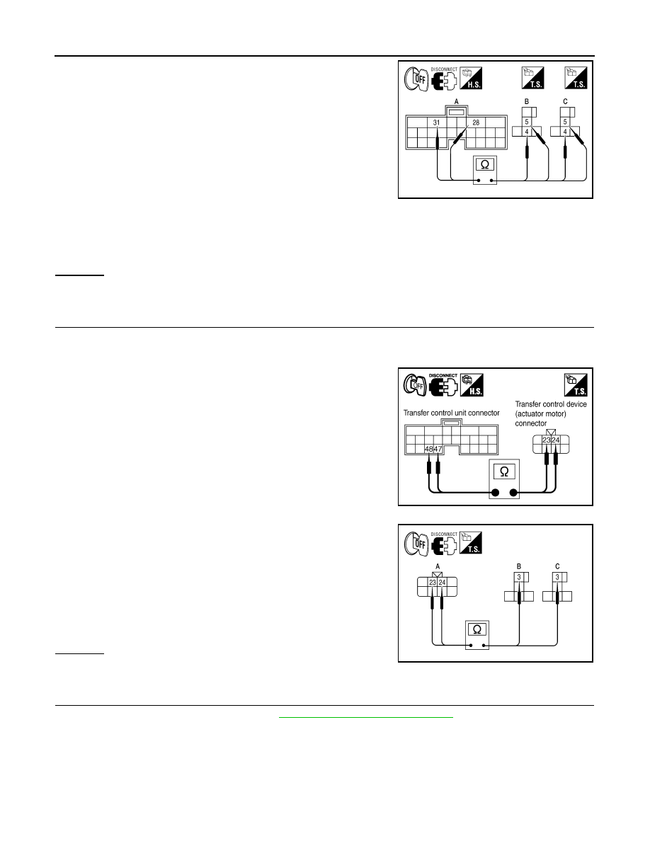
4. Check continuity between the following terminals.

-

Transfer control unit harness connector E143 (A) terminal 28

and transfer shift high relay harness connector E156 (B) termi-

nal 5.

-

Transfer control unit harness connector E143 (A) terminal 28

and transfer shift low relay harness connector E157 (C) terminal

5.

-

Transfer control unit harness connector E143 (A) terminal 31

and transfer shift high relay harness connector E156 (B) termi-

nal 4.

-

Transfer control unit harness connector E143 (A) terminal 31

and transfer shift low relay harness connector E157 (C) terminal

4.

Also check harness for short to ground and short to power.

OK or NG

OK

>> GO TO 7.

NG

>> Repair or replace damaged parts.

7.

CHECK ACTUATOR MOTOR OPERATION CIRCUIT

1. Turn ignition switch OFF.  (Stay for at least 5 seconds.)

2. Disconnect transfer control unit harness connector and the transfer control device harness connector.

3. Check continuity between the following terminals.

-

Transfer control unit harness connector E143 terminal 48 and

transfer control device (actuator motor) harness connector F58

terminal 23.

-

Transfer control unit harness connector E143 terminal 47 and

transfer control device (actuator motor) harness connector F58

terminal 24.

-

Transfer control device (actuator motor) harness connector F58

(A) terminal 24 and transfer shift high relay harness connector

E156 (B) terminal 3.

-

Transfer control device (actuator motor) harness connector F58

(A) terminal 23 and transfer shift low relay harness connector

E157 (C) terminal 3.

Also check harness for short to ground and short to power.

OK or NG

OK

>> GO TO 8.

NG

>> Repair or replace damaged parts.

8.

CHECK ACTUATOR MOTOR

1. Remove transfer control device. Refer to 

DLN-96, "Removal and Installation"

.

Continuity should exist.

AWDIA0056ZZ

SDIA2811E

Continuity should exist.

WDIA0323E

P1817 ACTUATOR MOTOR

DLN-45

< DTC/CIRCUIT DIAGNOSIS >

[TRANSFER: TX15B]

C

E

F

G

H

I

J

K

L

M

A

B

DLN

N

O

P

2. Check operation by applying battery voltage to transfer control

device (actuator motor) terminals 23 and 24.

CAUTION:

Be careful not to overheat the harness.

Does actuator motor rotate?

YES

>> GO TO 9.

NO

>> Replace transfer control device.

9.

CHECK TRANSFER CONTROL UNIT

Check transfer control unit input/output signal. Refer to 

DLN-56, "Reference Value"

.

OK or NG

OK

>> GO TO 10.

NG

>> Check transfer control unit pin terminals for damage or loose connection with harness connector.

If any items are damaged, repair or replace damaged parts.

10.

CHECK DTC

Perform the self-diagnosis, after driving a vehicle for a while.
OK or NG

OK

>> Inspection End.

NG

>> Replace transfer control unit. Refer to 

DLN-91, "Removal and Installation"

.

Component Inspection

INFOID:0000000009885990

ACTUATOR MOTOR

1. Remove transfer control device. Refer to 

DLN-96, "Removal and Installation"

.

2. Check operation by applying battery voltage to transfer control

device (actuator motor) terminals 23 and 24.

CAUTION:

Be careful not to overheat the harness.

3. If the inspection results are abnormal replace the transfer control

device.

TRANSFER RELAY

1. Turn ignition switch “OFF”.  (Stay for at least 5 seconds.)
2. Remove transfer shift high relay and transfer shift low relay. Refer to 

DLN-12, "Component Parts Location"

.

3. Apply 12V direct current between transfer relay terminals 1 and 2.

Terminal

Actuator motor

24 (Battery voltage) - 23 (Ground)

Clockwise rotate

23 (Battery voltage) - 24 (Ground)

Counterclockwise rotate

SDIA2386E

Terminal

Actuator motor

24 (Battery voltage) - 23 (Ground)

Clockwise rotate

23 (Battery voltage) - 24 (Ground)

Counterclockwise rotate

SDIA2386E

DLN-46

< DTC/CIRCUIT DIAGNOSIS >

[TRANSFER: TX15B]

P1817 ACTUATOR MOTOR

4. Check continuity between relay terminals 3 and 4, and 3 and 5.

5. If NG, replace transfer shift high or low relay.

Terminal

Condition

Continuity

3 - 4

12V direct current supply between terminals 1 and 2

No

OFF

Yes

3 - 5

12V direct current supply between terminals 1 and 2

Yes

OFF

No

WIIA0291E

P1818 ACTUATOR POSITION SWITCH

DLN-47

< DTC/CIRCUIT DIAGNOSIS >

[TRANSFER: TX15B]

C

E

F

G

H

I

J

K

L

M

A

B

DLN

N

O

P

P1818 ACTUATOR POSITION SWITCH

Description

INFOID:0000000009885991

The actuator position switch detects the current actuator motor range.  DTC P1818 or flash code 12 will set if

either of the following occur:

• Improper signal from actuator position switch is input due to open or short circuit.

• Malfunction is detected in actuator position switch.

DTC Logic

INFOID:0000000009885992

DTC DETECTION LOGIC

DTC CONFIRMATION PROCEDURE

1.

DTC CONFIRMATION PROCEDURE

1. Turn ignition switch ON.

2. Perform self-diagnosis.
Is DTC P1818 or flash code 12 detected?

YES

>> Perform diagnosis procedure. Refer to 

DLN-47, "Diagnosis Procedure"

.

NO

>> Inspection End.

Diagnosis Procedure

INFOID:0000000009885993

Regarding Wiring Diagram information, refer to 

DLN-62, "Wiring Diagram"

.

1.

CHECK ACTUATOR POSITION SWITCH SIGNAL

With CONSULT

1. Start engine.

2. Depress brake pedal and stop vehicle.

3. Set A/T selector lever to N position.

4. Select DATA MONITOR mode for ALL MODE AWD/4WD with CONSULT.

5. Read out the value of SHIFT POS SW1, SHIFT POS SW2, SHIFT POS SW3, SHIFT POS SW4.

Without CONSULT

1. Start engine.

DTC

CONSULT

Diagnostic item is detected when...

Reference

[P1818]

SHIFT ACT POSI SW

• Improper signal from actuator position 

switch is input due to open or short cir-
cuit.

• Malfunction is detected in actuator po-

sition switch.

DLN-47, "Diagnosis Procedure"

Monitored item

Condition

Display value

SHIFT POS SW1

4WD shift switch: 2WD and 4LO

ON

4WD shift switch: 4H

OFF

SHIFT POS SW2

4WD shift switch: 4LO

ON

4WD shift switch: 2WD and 4H

OFF

SHIFT POS SW3

4WD shift switch: 2WD and 4H

ON

4WD shift switch: 4LO

OFF

SHIFT POS SW4

4WD shift switch: 4H and 4LO

ON

4WD shift switch: 2WD

OFF


Content   ..  116  117  118  119   ..