Nissan Titan. Manual - part 72


  Index      Nissan     Nissan Titan (2014 year) - Service and Repair Manual


Search            


Content   ..  70  71  72  73   ..


Nissan Titan. Manual - part 72


WATER PUMP

CO-21

< REMOVAL AND INSTALLATION >

C

D

E

F

G

H

I

J

K

L

M

A

CO

N

P

O

INSTALLATION

Installation is in the reverse order of removal.

• After installation bleed the air from the cooling system. Refer to 

CO-11, "Changing Engine Coolant"

.

INSPECTION AFTER INSTALLATION

• Before starting engine, check oil/fluid levels including engine coolant and engine oil. If less than required

quantity, fill to the specified level. Refer to 

MA-15, "FOR NORTH AMERICA : Fluids and Lubricants"

 (United

States and Canada) or 

MA-16, "FOR MEXICO : Fluids and Lubricants"

 (Mexico).

• Use procedure below to check for fuel leakage.

• Turn ignition switch ON (with engine stopped). With fuel pressure applied to fuel piping, check for fuel leak-

age at connection points.

• Start engine. With engine speed increased, check again for fuel leakage at connection points.

• Run engine to check for unusual noise and vibration.

NOTE:

If hydraulic pressure inside timing chain tensioner drops after removal and installation, slack in the guide

may generate a pounding noise during and just after engine start. However, this is normal. Noise will stop

after hydraulic pressure rises.

• Warm up engine thoroughly to make sure there is no leakage of fuel, exhaust gas, or any oils/fluids including

engine oil and engine coolant.

• Bleed air from passages in lines and hoses, such as in cooling system.

• After cooling down engine, again check oil/fluid levels including engine oil and engine coolant. Refill to spec-

ified level, if necessary.

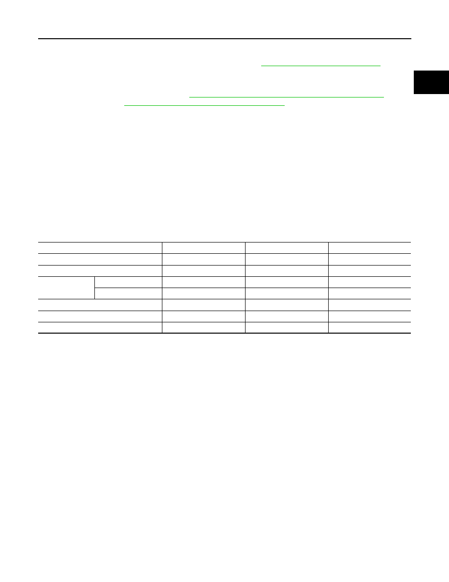
• Summary of the inspection items:

*Power steering fluid, brake fluid, etc.

Item

Before starting engine

Engine running

After engine stopped

Engine coolant

Level

Leakage

Level

Engine oil

Level

Leakage

Level

Transmission/
transaxle fluid 

A/T and CVT Models

Leakage

Level/Leakage

Leakage

M/T Models

Level/Leakage

Leakage

Level/Leakage

Other oils and fluids*

Level

Leakage

Level

Fuel

Leakage

Leakage

Leakage

Exhaust gas

Leakage

CO-22

< REMOVAL AND INSTALLATION >

THERMOSTAT AND WATER PIPING

THERMOSTAT AND WATER PIPING

Exploded View

INFOID:0000000009886481

Removal and Installation

INFOID:0000000009886482

WARNING:

Do not remove the radiator cap when the engine is hot. Serious burns could occur from high-pressure

engine coolant escaping from the radiator. Wrap a thick cloth around the radiator cap. Slowly turn it a

quarter of a turn to release built-up pressure. Carefully remove radiator cap by turning it all the way.

CAUTION:

• When removing water pump, be careful not to get engine coolant on drive belt.

• Water pump cannot be disassembled and should be replaced as a unit.

• After installing water pump, connect hoses and clamps securely, then check for leaks.

• Perform when engine is cold.

NOTE:

When removing components such as hoses, tubes/lines, etc., cap or plug openings to prevent fluid from spill-

ing.

REMOVAL

Removal of Thermostat

1. Partially drain engine coolant from the radiator. Refer to 

CO-11, "Changing Engine Coolant"

.

1.

Heater pipe

2.

Gasket

3.

Water outlet

4.

Gasket

5.

O-ring

6.

O-ring

7.

Thermostat housing

8.

Rubber ring

9.

Thermostat

10.

Water inlet

11.

Water suction hose

12. Water suction pipe

13.

Gasket

14. Heater pipe

KBIA2501E

THERMOSTAT AND WATER PIPING

CO-23

< REMOVAL AND INSTALLATION >

C

D

E

F

G

H

I

J

K

L

M

A

CO

N

P

O

2. Disconnect the water suction hose from the water inlet.
3. Remove the water inlet and thermostat.

Removal of Thermostat Housing, Water Outlet and Heater Pipe

1. Remove the intake manifold. Refer to 

EM-27, "Removal and Installation"

.

2. Remove the thermostat housing, water outlet and heater pipe.

Removal of Water Cut Valve

1. Partially drain engine coolant from the radiator. Refer to 

CO-11, "Changing Engine Coolant"

.

CAUTION:

Perform when the engine is cold.

2. Disconnect the water cut valve connector.
3. Disconnect the water hoses from the water cut valve.
4. Remove the water cut valve.

INSPECTION AFTER REMOVAL

• Place a thread so that it is caught in the valve of the thermostat.

Immerse fully in a container filled with water. Heat while stirring.

• The valve opening temperature is the temperature at which the

valve opens and falls from the thread. 

• Continue heating. Check the full-open lift amount.

• After checking the full-open lift amount, lower the water tempera-

ture and check the valve closing temperature.

Replace the thermostat if the valve opening or closing values are out of the specification range.

INSTALLATION

Installation is in the reverse order of removal.

Installation of Thermostat 

Installation is in the reverse order of removal.

• Install the thermostat with the flange securely inside the rubber ring

as shown. 

• Install the thermostat with the jiggle valve facing upwards. 

Installation of Water Outlet Pipe and Heater Pipe

Installation is in the reverse order of removal.

Apply a mild detergent to the O-rings before installing the water outlet pipe and heater pipe. 

INSPECTION AFTER INSTALLATION

• Check for engine coolant leaks. Refer to 

CO-10, "Inspection"

.

• Start and warm up the engine. Visually check for engine coolant leaks.

SLC252B

Thermostat

Standard values

Valve opening temperature

Refer to 

CO-24, "Standard and Limit"

.

Full-open lift amount

Refer to 

CO-24, "Standard and Limit"

.

Valve closing temperature

Refer to 

CO-24, "Standard and Limit"

.

KBIA2502E

CO-24

< SERVICE DATA AND SPECIFICATIONS (SDS) 

SERVICE DATA AND SPECIFICATIONS (SDS)

SERVICE DATA AND SPECIFICATIONS (SDS)

SERVICE DATA AND SPECIFICATIONS (SDS)

Standard and Limit

INFOID:0000000009886483

ENGINE COOLANT CAPACITY (APPROXIMATE)

Unit:   (US qt, Imp qt)

THERMOSTAT

RADIATOR

Unit: kPa (kg/cm

2

, psi)

Engine coolant capacity (With reservoir at "MAX" level)

12.2 (12-7/8, 10-3/4)

Valve opening temperature

80

° - 84°C (176° - 183°F)

Full-open lift amount

More than 10 mm / 95

°C (0.39 in / 203°F)

Valve closing temperature

77

°C (171°F) or higher

Reservoir cap relief pressure

Standard

110 (1.12, 16)

Test pressure

137 (1.4, 20)


Content   ..  70  71  72  73   ..