Nissan Titan. Manual - part 25
C1113, C1145, C1146 YAW RATE/SIDE/DECEL G SENSOR
BRC-41
< DTC/CIRCUIT DIAGNOSIS >
[VDC/TCS/ABS]
C
D
E
G
H
I
J
K
L
M
A
B
BRC
N
O
P
Is the inspection result normal?
YES
>> GO TO 3
NO
>> Repair or replace as necessary.
3.
YAW RATE/SIDE/DECEL G SENSOR INSPECTION
1. Connect the yaw rate/side/decel G sensor and ABS actuator and electric unit (control unit) connectors.
2. Perform the yaw rate/side/decel G sensor component inspection. Refer to
Is the inspection result normal?
YES
>> Replace the ABS actuator and electric unit (control unit). Refer to
.
NO
>> Replace the yaw rate/side/decel G sensor and perform calibration of decel G-sensor. Refer to
BRC-119, "Removal and Installation"
.
Component Inspection
INFOID:0000000009883629
1.
CHECK DATA MONITOR
Select “YAW RATE SEN”, “SIDE G-SENSOR”, “DECEL G-SEN” in “DATA MONITOR” and check yaw rate/
side/decel G sensor signal.
Is the inspection result normal?
YES
>> Inspection End
NO
>> Go to diagnosis procedure. Refer to
Special Repair Requirement
INFOID:0000000009883630
1.
ADJUSTMENT OF STEERING ANGLE SENSOR NEUTRAL POSITION
Always perform neutral position adjustment for the steering angle sensor when replacing the ABS actuator
and electric unit (control unit). Refer to
BRC-8, "ADJUSTMENT OF STEERING ANGLE SENSOR NEUTRAL
.
>> GO TO 2
2.
CALIBRATION OF DECEL G SENSOR
Always perform calibration of decel G sensor when replacing the ABS actuator and electric unit (control unit).
BRC-9, "CALIBRATION OF DECEL G SENSOR : Description"
>> END
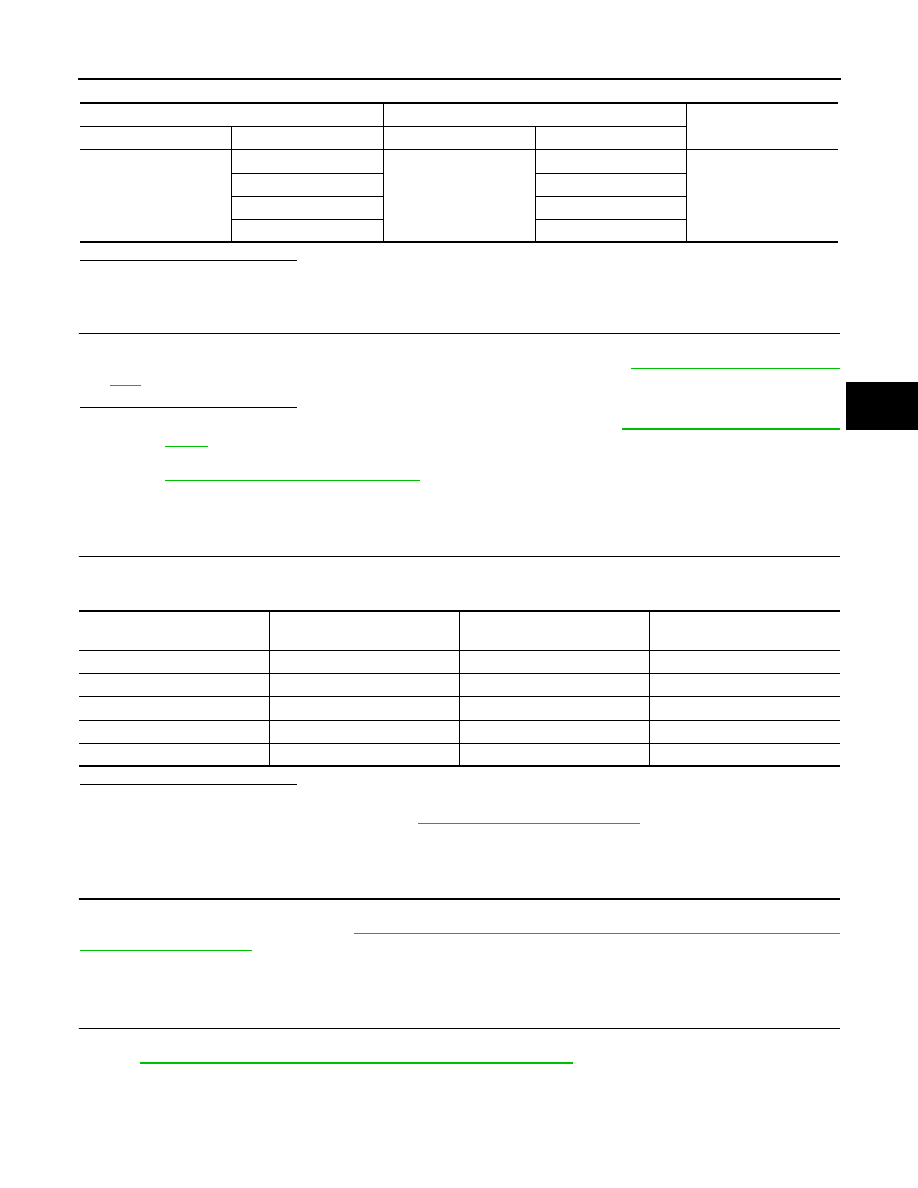
ABS actuator and electric unit (control unit)
Yaw rate/side/decel G sensor
Continuity
Connector
Terminal
Connector
Terminal
E125
6
M108
4
Yes
24
1
25
2
29
3
Vehicle condition
YAW RATE SEN
(DATA MONITOR)
SIDE G-SENSOR
(DATA MONITOR)
DECEL G-SEN
(DATA MONITOR)
Stopped
-4 to +4 deg/s
-1.1 to +1.1 m/s
-0.11 G to +0.11 G
Turning right
Negative value
Negative value
-
Turning left
Positive value
Positive value
-
Speed up
-
-
Negative value
Speed down
-
-
Positive value