Nissan Titan A60. Manual - part 848
SEC-30
< DTC/CIRCUIT DIAGNOSIS >
KEY CYLINDER SWITCH
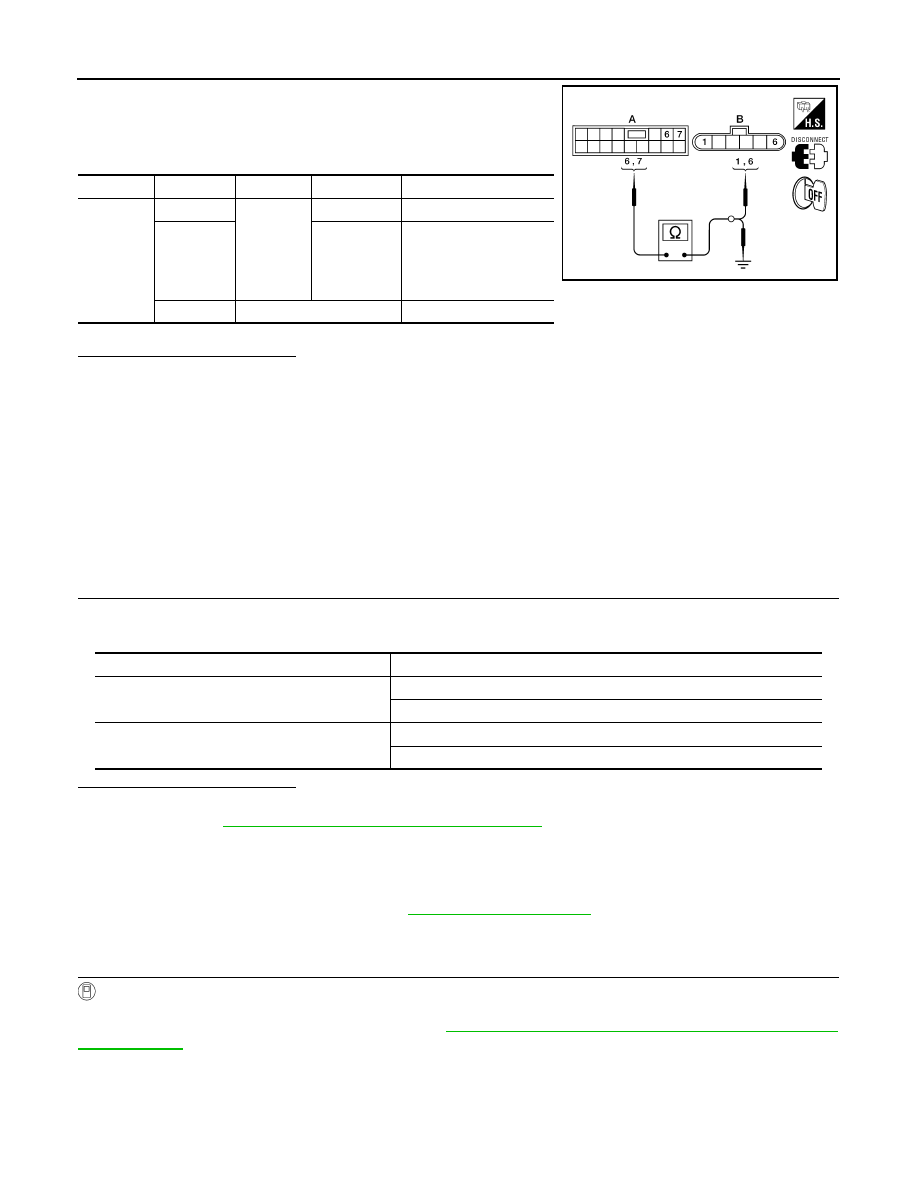
2. Check continuity between main power window and door lock/
unlock switch connector (A) D15 terminals 6, 7 and front door
lock assembly LH (key cylinder switch) connector (B) D14 termi-
nals 1, 6 and body ground.
Is the inspection result normal?
YES
>> Replace main power window and door lock/unlock switch.
NO
>> Repair or replace harness.
CREW CAB
CREW CAB : Description
INFOID:0000000006161591
The main power window and door lock/unlock switch detects condition of the door key cylinder switch and
transmits to BCM as the LOCK or UNLOCK signal.
CREW CAB : Component Function Check
INFOID:0000000006161592
1.
CHECK DOOR KEY CYLINDER SWITCH INPUT SIGNAL
Check "KEY CYL LK-SW" AND "KEY CYL UN-SW" in DATA MONITOR mode for “POWER DOOR LOCK
SYSTEM” with CONSULT-III.
Is the inspection result normal?
YES
>> Key cylinder switch is OK.
NO
>> Refer to
SEC-30, "CREW CAB : Diagnosis Procedure"
CREW CAB : Diagnosis Procedure
INFOID:0000000006161593
Regarding Wiring Diagram information, refer to
.
1.
CHECK DOOR KEY CYLINDER SWITCH LH
With CONSULT-III
Check front door lock assembly LH (key cylinder switch) ("KEY CYL LK-SW") and ("KEY CYL UN-SW) in
DATA MONITOR mode with CONSULT–III. Refer to
BCS-16, "DOOR LOCK : CONSULT-III Function (BCM -
.
• When key inserted in front key cylinder is turned to LOCK:
• When key inserted in front key cylinder is turned to UNLOCK:
Connector
Terminals
Connector
Terminals
Continuity
A: Main
power win-
dow and
door lock/
unlock
switch
6
B: Front
door lock
assembly
LH (key
cylinder
switch)
1
Yes
7
6
Yes
6, 7
Ground
No
LIIA2360E
Monitor item
Condition
KEY CYL LK-SW
Lock
: ON
Neutral / Unlock
: OFF
KEY CYL UN-SW
Unlock
: ON
Neutral / Lock
: OFF
KEY CYL LK-SW
: ON