Nissan Titan A60. Manual - part 805
PWO
POWER SOCKET
PWO-7
< REMOVAL AND INSTALLATION >
C
D
E
F
G
H
I
J
K
L
B
A
O
P
N
REMOVAL AND INSTALLATION
POWER SOCKET
Removal and Installation
INFOID:0000000006710629
FRONT POWER SOCKET RH/LH, FRONT POWER SOCKET (CENTER ARMREST), CONSOLE
POWER SOCKET.
NOTE:
If the tool does not fit because of the location of the power socket, further disassembly of interior components
may be required. Refer to
IP-14, "Removal and Installation"
(Center console).
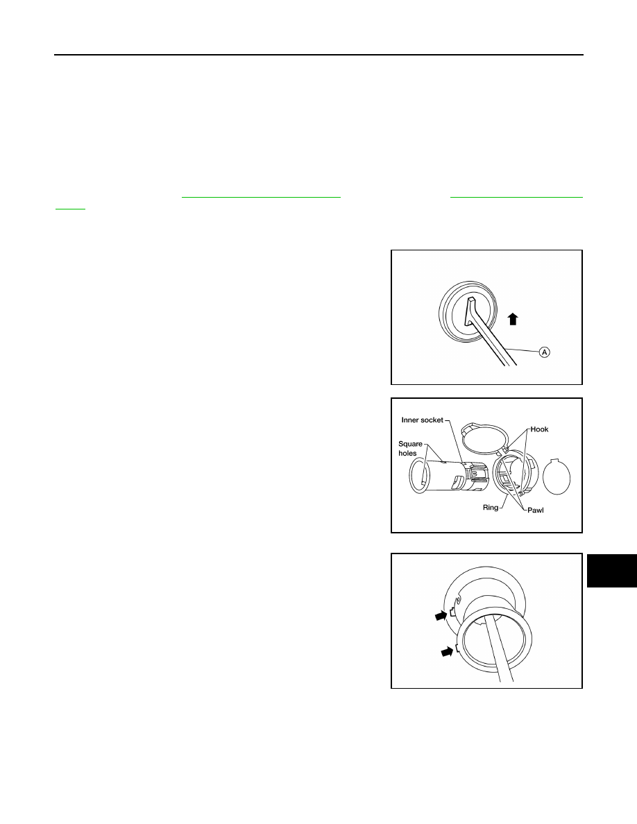
Removal
1. Remove the fuse for the power socket.
2. Insert one end of the Tool (A) into one of the square holes inside
the power socket.
3. Lift up the handle of the Tool until the other end of the Tool is
inside the socket and snaps into the other square hole in the
power socket.
4. Pull the power socket straight out with the Tool.
5. Disconnect power socket connector.
6. Remove ring from power socket finisher while pressing pawls.
Installation
Installation is in the reverse order of removal.
NOTE:
Make sure to align the tab with the square notched area during
installation.
REAR CARGO POWER SOCKET (CARGO BED)
Removal
1. Remove the fuse for the power socket.
2. Remove the rivets attaching the rear cargo power socket finisher to the cargo bed.
3. Disconnect power socket connector.
Installation
Tool number:
— (J-42059)
AWMIA1182GB
WKIA1035E
AWMIA1183GB