Nissan Titan A60. Manual - part 788
PWC-56
< DTC/CIRCUIT DIAGNOSIS >
POWER WINDOW SERIAL LINK
FRONT POWER WINDOW SWITCH : Component Function Check
INFOID:0000000006161093
1.
CHECK POWER WINDOW AND DOOR LOCK/UNLOCK SWITCH RH OUTPUT SIGNAL
Check (“CDL LOCK SW ”, “CDL UNLOCK SW”) in “DATA MONITOR” mode for “POWER DOOR LOCK SYS-
TEM” with CONSULT-III. Refer to
BCS-16, "DOOR LOCK : CONSULT-III Function (BCM - DOOR LOCK)"
.
Is the inspection result normal?
YES
>> Power window serial link is OK.
NO
>> Refer to
PWC-56, "FRONT POWER WINDOW SWITCH : Diagnosis Procedure"
FRONT POWER WINDOW SWITCH : Diagnosis Procedure
INFOID:0000000006161094
Regarding Wiring Diagram information, refer to
PWC-88, "Wiring Diagram - Crew Cab"
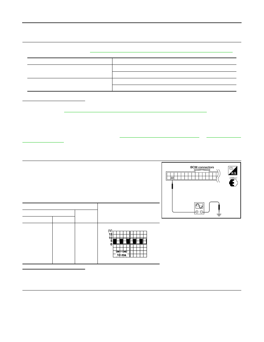
1.
CHECK POWER WINDOW AND DOOR LOCK/UNLOCK SWITCH RH
1. Remove ignition key, and close the front door LH and RH.
2. Check signal between BCM connector and ground with oscillo-
scope when door lock and unlock switch (LH and RH) is turned
to “LOCK” or “UNLOCK”.
3. Check that signals which are shown in the figure below can be
detected during 10 second just after door lock and unlock switch
(LH and RH) is turned to “LOCK” or “UNLOCK”.
Is the inspection result normal?
YES
>> Power window serial link is OK.
NO
>> GO TO 2
2.
CHECK POWER WINDOW SERIAL LINK CIRCUIT
Monitor item
Condition
CDL LOCK SW
LOCK
: ON
UNLOCK
: OFF
CDL UNLOCK SW
LOCK
: OFF
UNLOCK
: ON
Terminal
Signal
(Reference value)
(+)
(–)
BCM connector
Terminal
M18
22
Ground
LIIA0391E
PIIA1297E