Nissan Titan A60. Manual - part 776


  Index      Nissan     Nissan Titan A60 (2011 year) - Service and Repair Manual


Search            


Content   ..  774  775  776  777   ..


Nissan Titan A60. Manual - part 776


PWC-8

< SYSTEM DESCRIPTION >

POWER WINDOW SYSTEM

Hold the door key cylinder to the LOCK or UNLOCK direction for more than 1 second to OPEN or CLOSE front

power windows when ignition switch is OFF. In addition, it stops when key position is moved to NEUTRAL

when operating.

OPERATION CONDITION 

• Ignition switch OFF.

• Hold door key cylinder to LOCK position for more than 1 second to perform CLOSE operation of the door

glass.

• Hold door key cylinder to UNLOCK position for more than 1 second to perform OPEN operation of the door

glass.

KEYLESS POWER WINDOW DOWN OPERATION (FRONT LH & RH)

Front power windows open when the unlock button on keyfob is activated and kept pressed for more than
3

(NOTE)

 seconds with the ignition switch OFF. The windows keep opening if the unlock button is continuously

pressed.

The power window opening stops when the following operations are performed:

• When the unlock button is kept pressed more than 15 seconds.

• When the ignition switch is turned ON while the power window opening is operated.

• When the unlock button is released.

While retained power operation activate, keyless power window down function cannot be operated.

NOTE:

Keyless power window down operation mode can be changed by “PW DOWN SET” mode in “WORK SUP-

PORT”. Refer to 

BCS-18, "MULTI REMOTE ENT : CONSULT-III Function (BCM - MULTI REMOTE ENT)"

.

NOTE:

Use CONSULT-III to change settings.

MODE1 (3sec)/MODE2 (OFF)/MODE3 (5sec)

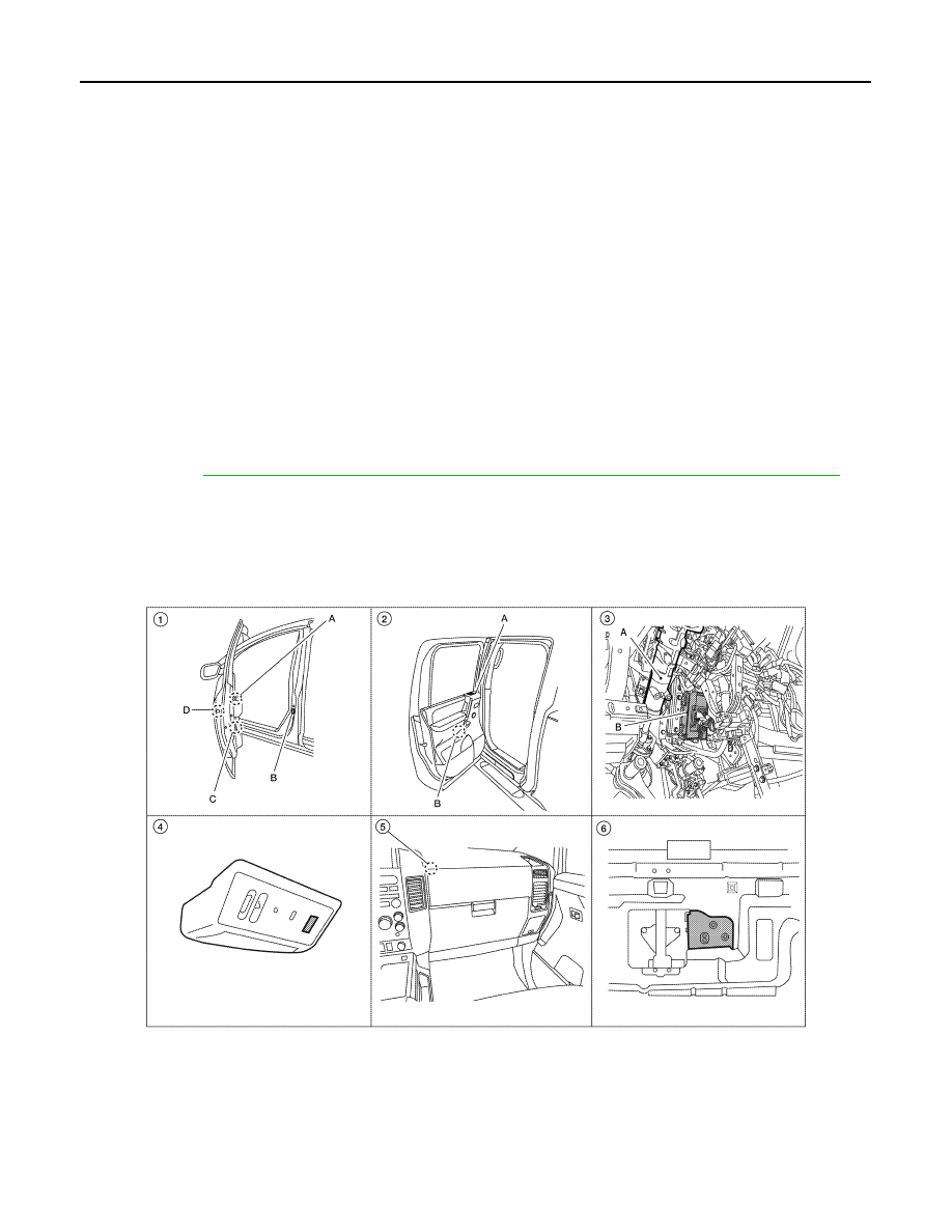
Component Parts Location

INFOID:0000000006161026

AWKIA1326ZZ

POWER WINDOW SYSTEM

PWC-9

< SYSTEM DESCRIPTION >

C

D

E

F

G

H

I

J

L

M

A

B

PWC

N

O

P

Component Description

INFOID:0000000006161027

POWER WINDOW SYSTEM

1.

A. Main power window and door 
lock/unlock switch D7, D8 (Crew 
Cab), D15 (King Cab)
Power window and door lock/unlock 
switch RH D105
B. Front door switch LH B8, RH B108
C. Front power window motor LH D9, 
RH D104
D. Front door lock assembly LH (key 
cylinder switch) D14

2.

A. Rear power window switch LH 
D203, RH D303 (Crew Cab)
B. Rear power window motor LH 
D204, RH D304 (Crew Cab)

3.

A. Steering column (view with instru-
ment panel removed)
B. BCM M18, M19, M20

4.

Rear power drop glass switch R103 
(Crew Cab)

5.

Rear power drop glass up relay 
M154 (Crew Cab)
Rear power drop glass down relay 
M155 (Crew Cab)

6.

Rear power drop glass motor B80 
(view with rear finisher removed) 
(Crew Cab)

Component

Function

BCM

• Supplies power supply to power window switch.
• Controls retained power.

Main power window and door lock/unlock 
switch

• Directly controls all power window motor of all doors.
• Controls anti-pinch operation of front power window LH.

Power window and door lock/unlock 
switch RH

• Controls front power window motor RH.
• Controls anti-pinch operation of front power window RH.

Rear power window switch (Crew Cab)

• Controls rear power window motors LH and RH.

Rear power drop glass switch (Crew Cab) • Controls rear power drop glass motor.

Front power window motor LH

• Integrates the ENCODER POWER and WINDOW MOTOR.
• Starts operating with signals from main power window and door lock/unlock switch.
• Transmits power window motor rotation as a pulse signal to main power window and 

door lock/unlock switch.

Front power window motor RH

Starts operating with signals from main power window and door lock/unlock switch & 
power window and door lock/unlock switch RH.

Rear power window motor (Crew Cab)

Starts operating with signals from main power window and door lock/unlock switch & 
rear power window switch.

Rear power drop glass motor (Crew Cab)

Starts operating with signal from rear power drop glass switch.

Front door lock assembly LH (key cylinder 
switch)

Transmits operation condition of key cylinder switch to power window main switch.

Front door switch LH or RH

Detects door open/close condition and transmits to BCM.

PWC-10

< SYSTEM DESCRIPTION >

DIAGNOSIS SYSTEM (BCM)

DIAGNOSIS SYSTEM (BCM)

COMMON ITEM
COMMON ITEM : CONSULT-III Function (BCM - COMMON ITEM)

INFOID:0000000006628740

APPLICATION ITEM

CONSULT-III performs the following functions via CAN communication with BCM.

SYSTEM APPLICATION

BCM can perform the following functions.

RETAINED PWR

Direct Diagnostic Mode

Description

Ecu Identification

The BCM part number is displayed.

Self Diagnostic Result

The BCM self diagnostic results are displayed.

Data Monitor

The BCM input/output data is displayed in real time.

Active Test

The BCM activates outputs to test components.

Work support

The settings for BCM functions can be changed.

Configuration

• The vehicle specification can be read and saved.
• The vehicle specification can be written when replacing BCM.

CAN Diag Support Mntr

The result of transmit/receive diagnosis of CAN communication is displayed.

System

Sub System

Direct Diagnostic Mode

E

cu

 Id

en

tifi

ca

tio

n

Se

lf Di

ag

no

st

ic Re

su

lt

Da

ta

 Mo

ni

tor

A

cti

ve

 T

est

W

o

rk support

Co

nf

igu

rat

ion

CA

N Diag

 Su

pp

ort Mn

tr

Door lock

DOOR LOCK

×

×

×

×

Rear window defogger

REAR DEFOGGER

×

×

Warning chime

BUZZER

×

×

Interior room lamp timer

INT LAMP

×

×

×

Remote keyless entry system

MULTI REMOTE ENT

×

×

×

Exterior lamp

HEADLAMP

×

×

×

Wiper and washer

WIPER

×

×

×

Turn signal and hazard warning lamps FLASHER

×

×

Air conditioner

AIR CONDITIONER

×

Combination switch

COMB SW

×

BCM

BCM

×

×

×

×

×

Immobilizer

IMMU

×

×

×

Interior room lamp battery saver

BATTERY SAVER

×

×

×

Vehicle security system

THEFT ALM

×

×

×

RAP system

RETAINED PWR

×

×

×

Signal buffer system

SIGNAL BUFFER

×

×

TPMS

AIR PRESSURE MONITOR

×

×

×

×

Panic alarm system

PANIC ALARM

×

DIAGNOSIS SYSTEM (BCM)

PWC-11

< SYSTEM DESCRIPTION >

C

D

E

F

G

H

I

J

L

M

A

B

PWC

N

O

P

RETAINED PWR : CONSULT-III Function (BCM - RETAINED PWR)

INFOID:0000000006628741

DATA MONITOR

ACTIVE TEST

WORK SUPPORT

*: Initial setting

Monitor Item [Unit]

Description

IGN ON SW [On/Off]

Indicates condition of ignition switch ON position.

DOOR SW-DR [On/Off]

Indicates condition of front door switch LH.

DOOR SW-AS [On/Off]

Indicates condition of front door switch RH.

Test Item

Description

RETAINED PWR

This test is able to check retained power operation [Off/On].

Support Item

Setting

Description

RETAINED PWR SET

MODE3

2 min

Sets the retained accessory power operating time. 

MODE2

OFF

MODE1*

45 sec


Content   ..  774  775  776  777   ..