Nissan Titan A60. Manual - part 736


  Index      Nissan     Nissan Titan A60 (2011 year) - Service and Repair Manual


Search            


Content   ..  734  735  736  737   ..


Nissan Titan A60. Manual - part 736


MWI-58

< ECU DIAGNOSIS INFORMATION >

IPDM E/R (INTELLIGENT POWER DISTRIBUTION MODULE ENGINE ROOM)

Terminal Layout

INFOID:0000000006709549
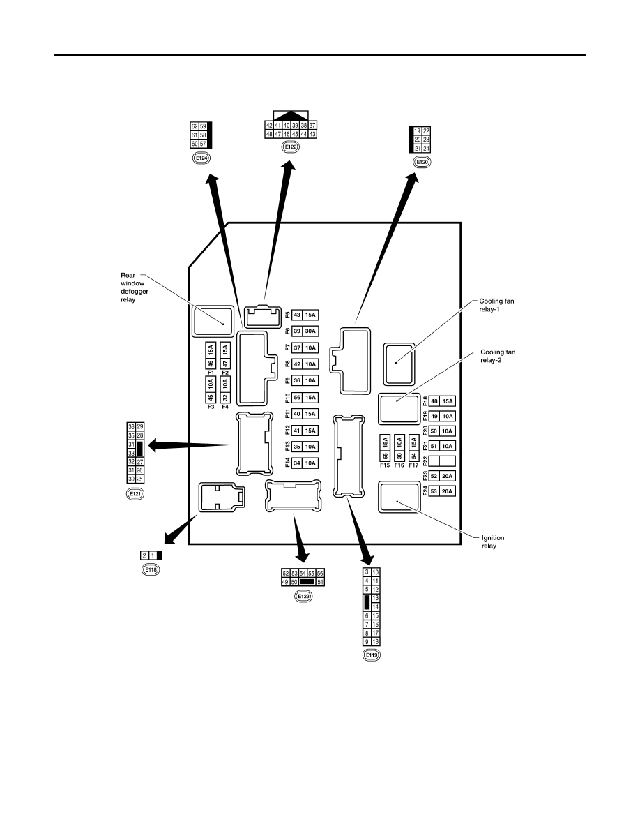
NOTE:

Numbers preceded by an "F" represent the fuse numbers imprinted on the IPDM E/R.  The other numbers rep-

resent the fuse numbers as they appear in the wiring diagrams.

Physical Values

INFOID:0000000006709550

PHYSICAL VALUES

AAMIA0386GB

MWI

IPDM E/R (INTELLIGENT POWER DISTRIBUTION MODULE ENGINE ROOM)

MWI-59

< ECU DIAGNOSIS INFORMATION >

C

D

E

F

G

H

I

J

K

L

M

B

A

O

P

Terminal

Wire

color

Signal name

Signal 

input/

output

Measuring condition

Reference value

(Approx.)

Igni-

tion 

switch

Operation or condition

1

B/Y

Battery power supply

Input

OFF

Battery voltage

2

R

Battery power supply

Input

OFF

Battery voltage

3

BR

ECM relay

Output

Ignition switch ON or START

Battery voltage

Ignition switch OFF or ACC

0V

4

W/L

ECM relay

Output

Ignition switch ON or START

Battery voltage

Ignition switch OFF or ACC

0V

6

L

Throttle control mo-
tor relay

Output

Ignition switch ON or START

Battery voltage

Ignition switch OFF or ACC

0V

7

W/B

ECM relay control

Input

Ignition switch ON or START

0V

Ignition switch OFF or ACC

Battery voltage

8

R/B

Fuse 54

Output

Ignition switch ON or START

Battery voltage

Ignition switch OFF or ACC

0V

10

G

Fuse 45
(Canada only)

Output

ON

Daytime light system active

0V

Daytime light system inactive

Battery voltage

11

Y/B

A/C compressor

Output

ON or 

START

A/C switch ON or defrost A/C switch

Battery voltage

A/C switch OFF or defrost A/C switch

0V

12

L/W

Ignition switch sup-
plied power

Input

OFF or ACC

0V

ON or START

Battery voltage

13

B/Y

Fuel pump relay

Output

Ignition switch ON or START

Battery voltage

Ignition switch OFF or ACC

0V

14

Y/R

Fuse 49

Output

Ignition switch ON or START

Battery voltage

Ignition switch OFF or ACC

0V

15

LG/B

Fuse 50

Output

Ignition switch ON or START

Battery voltage

Ignition switch OFF or ACC

0V

16

G

Fuse 51

Output

Ignition switch ON or START

Battery voltage

Ignition switch OFF or ACC

0V

17

W

Fuse 55

Output

Ignition switch ON or START

Battery voltage

Ignition switch OFF or ACC

0V

19

W/R

Starter motor

Output

START

Battery voltage

21

BR

Ignition switch sup-
plied power

Input

OFF or ACC

0V

START

Battery voltage

22

G

Battery power supply

Output

OFF

Battery voltage

23

GR/W

Door mirror defogger 
output signal (if 
equipped)

Output

When rear defogger switch is ON

Battery voltage

When rear defogger switch is OFF

0V

27

W/B

Fuse 38
(With trailer tow)

Output

Ignition switch ON or START

Battery voltage

Ignition switch OFF or ACC

0V

30

W

Fuse 53

Output

Ignition switch ON or START

Battery voltage

Ignition switch OFF or ACC

0V

32

L

Wiper low speed sig-
nal

Output

ON or 

START

Wiper switch

OFF

Battery voltage

LO or INT

0V

MWI-60

< ECU DIAGNOSIS INFORMATION >

IPDM E/R (INTELLIGENT POWER DISTRIBUTION MODULE ENGINE ROOM)

35

L/B

Wiper high speed 
signal

Output

ON or 

START

Wiper switch

OFF, LO, INT

Battery voltage

HI

0V

37

Y

Power generation 
command signal

Output

Ignition switch ON

6.3 V

40% is set on "Active test," "ALTER-
NATOR DUTY" of "ENGINE"

3.8 V

40% is set on "Active test," "ALTER-
NATOR DUTY" of "ENGINE"

1.4 V

38

B

Ground

Input

0V

39

L

CAN-H

ON

40

P

CAN-L

ON

42

GR

Oil pressure switch

Input

Engine running

Battery voltage

Engine stopped

0V

43

L/Y

Wiper auto stop sig-
nal

Input

ON or 

START

Wiper switch

OFF, LO, INT

Battery voltage

44

BR

Daytime light relay 
control
(Canada only)

Input

ON

Daytime light system active

0V

Daytime light system inactive

Battery voltage

45

G/W

Horn relay control

Input

ON

When door locks are operated using 
keyfob (OFF 

→ ON)*

Battery voltage 

→ 

0V

46

GR

Fuel pump relay con-
trol

Input

Ignition switch ON or START

0V

Ignition switch OFF or ACC

Battery voltage

47

O

Throttle control mo-
tor relay control

Input

Ignition switch ON or START

0V

Ignition switch OFF or ACC

Battery voltage

48

B/R

Starter relay (inhibit 
switch)

Input

ON or 

START

Selector lever in "P" or "N"

0V

Selector lever any other position

Battery voltage

Terminal

Wire

color

Signal name

Signal 

input/

output

Measuring condition

Reference value

(Approx.)

Igni-

tion 

switch

Operation or condition

JPMIA0001GB

JPMIA0002GB

JPMIA0003GB

MWI

IPDM E/R (INTELLIGENT POWER DISTRIBUTION MODULE ENGINE ROOM)

MWI-61

< ECU DIAGNOSIS INFORMATION >

C

D

E

F

G

H

I

J

K

L

M

B

A

O

P

*: When horn reminder is ON

Fail Safe

INFOID:0000000006709551

CAN COMMUNICATION CONTROL

When CAN communication with ECM and BCM is impossible, IPDM E/R performs fail-safe control. After CAN

communication recovers normally, it also returns to normal control.

If No CAN Communication Is Available With BCM

49

R/L

Trailer tow relay
(With trailer tow)
Illumination
(Without trailer tow)

Output

ON

Lighting switch 
must be in the 1st 
position

OFF

0V

ON

Battery voltage

50

W/R

Front fog lamp (LH) 
(if equipped)

Output

ON or 

START

Lighting switch 
must be in the 
2nd position 
(LOW beam is 
ON) and the front 
fog lamp switch

OFF

0V

ON

Battery voltage

51

W/R

Front fog lamp (RH) 
(if equipped)

Output

ON or 

START

Lighting switch 
must be in the 
2nd position 
(LOW beam is 
ON) and the front 
fog lamp switch

OFF

0V

ON

Battery voltage

52

L

LH low beam head-
lamp

Output

Lighting switch in 2nd position

Battery voltage

54

R/Y

RH low beam head-
lamp

Output

Lighting switch in 2nd position

Battery voltage

55

G

LH high beam head-
lamp

Output

Lighting switch in 2nd position and 
placed in HIGH or PASS position

Battery voltage

56

Y

(With DTRL)

L/W

(Without DTRL)

RH high beam head-
lamp

Output

Lighting switch in 2nd position and 
placed in HIGH or PASS position

Battery voltage

57

R/L

Parking, license, tail 
lamp and rear audio 
remote control unit

Output

ON

Lighting switch 
1st position

OFF

0V

ON

Battery voltage

59

B

Ground

Input

0V

60

B/W

Rear window defog-
ger relay (if 
equipped)

Output

ON or 

START

Rear defogger switch ON

Battery voltage

Rear defogger switch OFF

0V

61

BR

Fuse 32
(With trailer tow)

Output

OFF

Battery voltage

Terminal

Wire

color

Signal name

Signal 

input/

output

Measuring condition

Reference value

(Approx.)

Igni-

tion 

switch

Operation or condition

Control part

Fail-safe in operation

Headlamp

• Turns ON the headlamp low relay when the ignition switch is turned ON
• Turns OFF the headlamp low relay when the ignition switch is turned OFF
• Headlamp high LH/RH relays OFF

• Parking  lamps
• License plate lamps
• Tail lamps

• Turns ON the tail lamp relay when the ignition switch is turned ON
• Turns OFF the tail lamp relay when the ignition switch is turned OFF


Content   ..  734  735  736  737   ..