Nissan Titan A60. Manual - part 690
LAN-56
< SYSTEM DESCRIPTION >
[CAN]
TROUBLE DIAGNOSIS
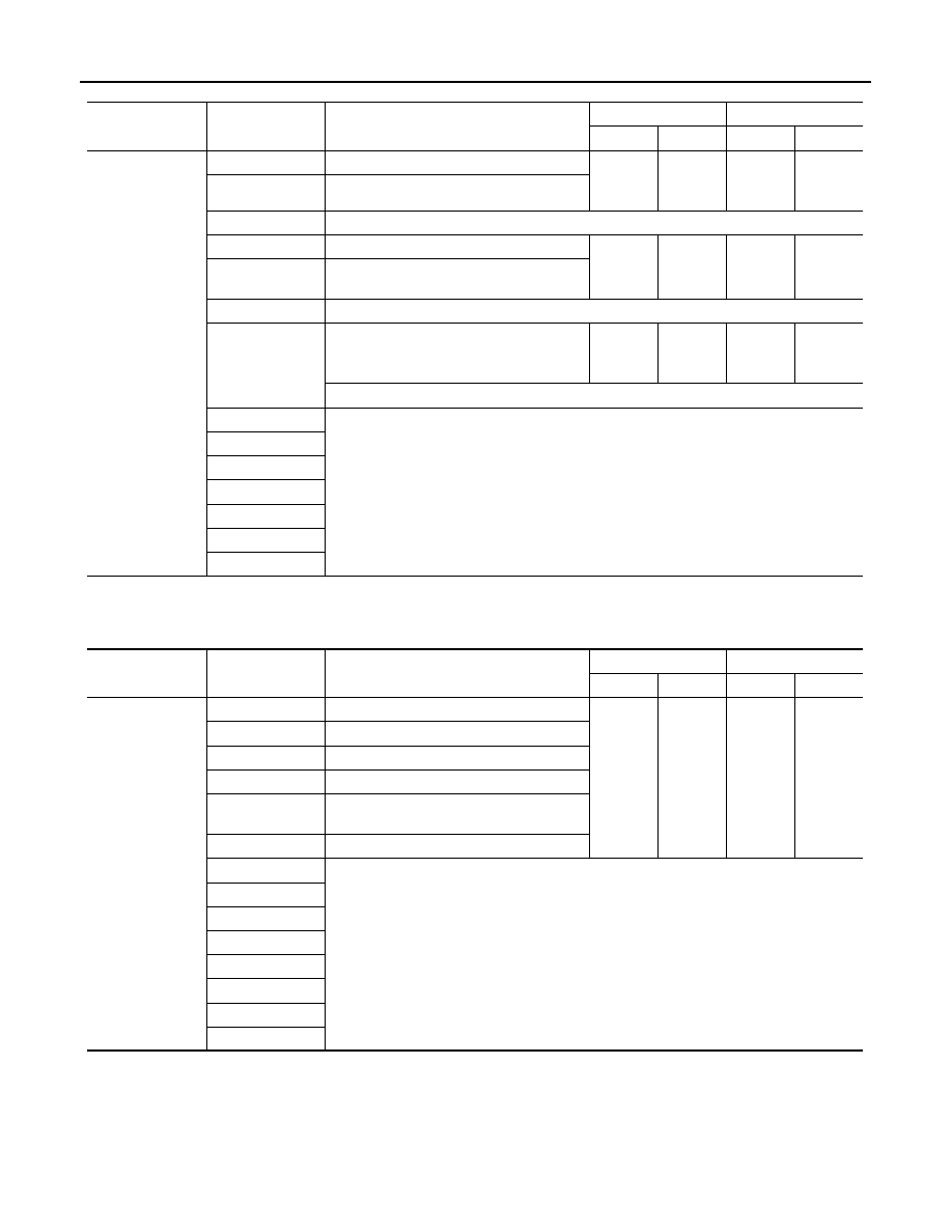
0: Error at present, 1 – 39: Error in the past (Number means the number of times the ignition switch is turned OFF
→ON)
*: 39 or higher number is fixed at 39 until the self-diagnosis result is erased.
Combination Meter
0: Error at present, 1 – 39: Error in the past (Number means the number of times the ignition switch is turned OFF
→ON)
*: 39 or higher number is fixed at 39 until the self-diagnosis result is erased.
Transfer Control Unit
NOTE:
Replace the unit when “NG” is indicated on the “INITIAL DIAG”.
ITEM
CAN DIAG SUP-
PORT MNTR
Description
Normal
Error
PRSNT
PAST
PRSNT
PAST
HVAC
TRANSMIT DIAG
Signal transmission status
OK
OK
or
1 – 39
*
UNKWN
0
ECM
Signal receiving status from the ECM
TCM
Not used even though indicated
BCM/SEC
Signal receiving status from the BCM
OK
OK
or
1 – 39
*
UNKWN
0
VDC/TCS/ABS
Signal receiving status from the ABS actua-
tor and electric unit (control unit)
IPDM E/R
Not used even though indicated
DISPLAY
With navigation system: Signal receiving
status from the display control unit
OK
OK
or
1 – 39
*
UNKWN
0
Without navigation system: Not used even though indicated
I-KEY
Not used even though indicated
EPS
AWD/4WD
e4WD
ICC/ADAS
LANE CAMERA
TIRE-P
ITEM
CAN DIAG SUP-
PORT MNTR
Description
Normal
Error
PRSNT
PAST
PRSNT
PAST
M&A
TRANSMIT DIAG
Signal transmission status
OK
OK
or
1 – 39
*
UNKWN
0
ECM
Signal receiving status from the ECM
TCM
Signal receiving status from the TCM
BCM/SEC
Signal receiving status from the BCM
VDC/TCS/ABS
Signal receiving status from the ABS actua-
tor and electric unit (control unit)
IPDM E/R
Signal receiving status from the IPDM E/R
DISPLAY
Not used even though indicated
I-KEY
EPS
AWD/4WD
e4WD
ICC/ADAS
LANE CAMERA
TIRE-P