Nissan Titan A60. Manual - part 635


  Index      Nissan     Nissan Titan A60 (2011 year) - Service and Repair Manual


Search            


Content   ..  633  634  635  636   ..


Nissan Titan A60. Manual - part 635


WATER VALVE CIRCUIT

HAC-223

< DTC/CIRCUIT DIAGNOSIS >

[MANUAL A/C (TYPE 2)]

C

D

E

F

G

H

J

K

L

M

A

B

HAC

N

O

P

NO

>> Repair harness or connector.

3.

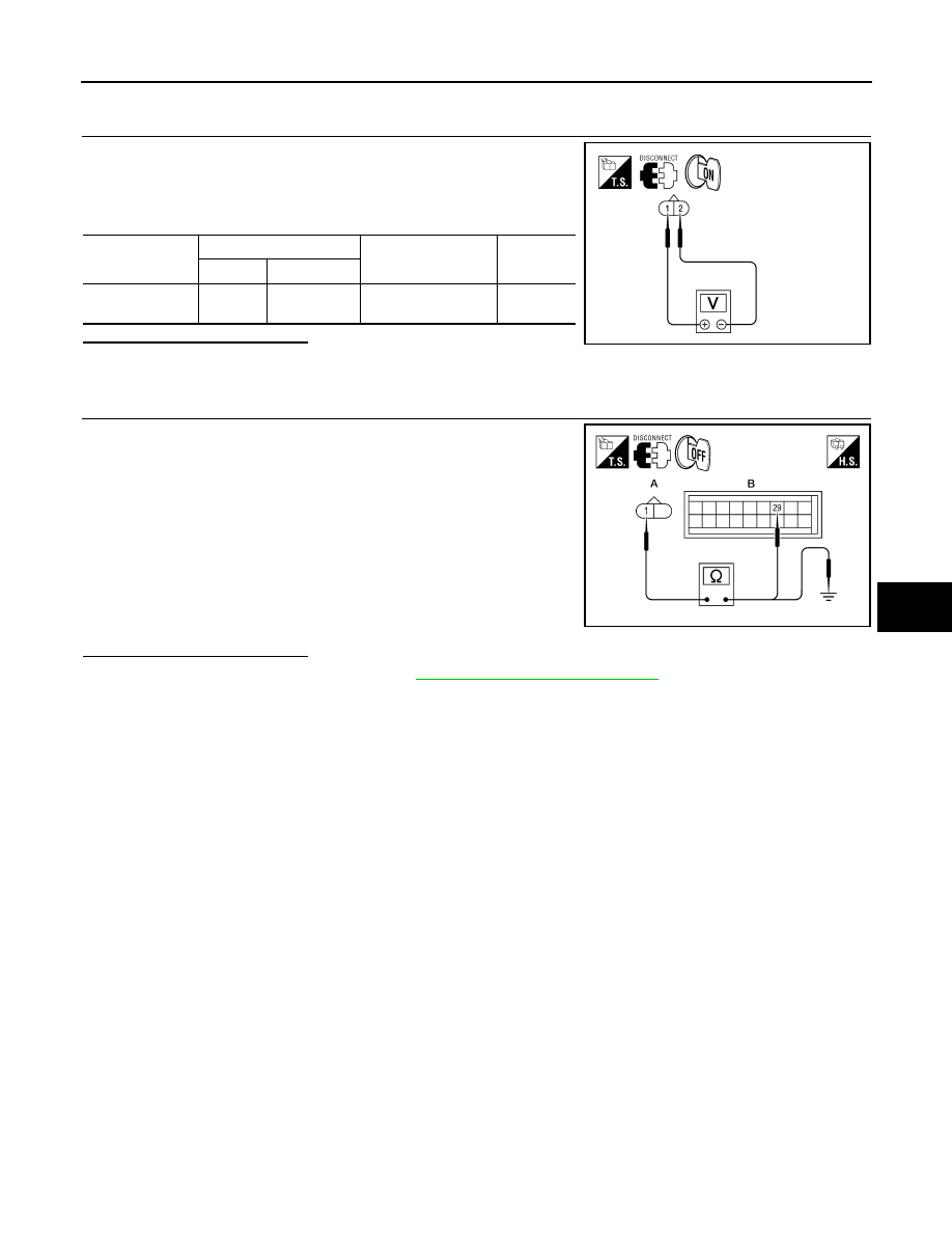
CHECK WATER VALVE POWER AND GROUND CIRCUITS

1. Rotate temperature control dial to maximum cold.

2. Check voltage between water valve harness connector F68 ter-

minal 1 and terminal 2 while rotating temperature control dial to

maximum heat. 

Is the inspection result normal?

YES

>>  Replace the water valve. 

NO

>> GO TO 4.

4.

CHECK WATER VALVE CONTROL OUTPUT CIRCUIT 

1. Turn ignition switch OFF.

2. Disconnect front air control connector M177.

3. Check continuity between water valve harness connector F68

(A) terminal 1 and front air control harness connector M177 (B)

terminal 29.

4. Check continuity between water valve harness connector F68

(A) terminal 1 and ground.

Is the inspection result normal?

YES

>> Replace front air control. Refer to 

VTL-8, "Removal and Installation"

.

NO

>> Repair harness or connector.

Connector

Terminals

Condition 

Voltage 

(Approx.)

(+) (-)

Water valve: F68

2

Rotate temperature 

control dial

Battery 
voltage

WJIA1792E

1 - 29

: Continuity should exist.

1 - Ground

: Continuity should not exist.

AWIIA0547ZZ

HAC-224

< DTC/CIRCUIT DIAGNOSIS >

[MANUAL A/C (TYPE 2)]

INTAKE SENSOR

INTAKE SENSOR

System Description

INFOID:0000000006164834

COMPONENT DESCRIPTION

Intake Sensor

The intake sensor (1) is located on the heater & cooling unit assem-

bly. It converts temperature of air after if passes through the evapo-

rator into a resistance value which is then input to the front air

control.

Intake Sensor Diagnosis Procedure

INFOID:0000000006164835

Regarding Wiring Diagram information, refer to 

HAC-232, "Wiring Diagram - Manual With 3 Control Dial Sys-

tem"

.

DIAGNOSTIC PROCEDURE FOR INTAKE SENSOR

SYMPTOM: Intake sensor circuit is open or shorted.

1.

CHECK VOLTAGE BETWEEN INTAKE SENSOR AND GROUND

1. Disconnect intake sensor connector.

2. Turn ignition switch ON.

3. Check voltage between intake sensor harness connector M146

terminal 2 and ground.

Is the inspection result normal?

YES

>> GO TO 2.

NO

>> GO TO 4.

2.

CHECK CIRCUIT CONTINUITY BETWEEN INTAKE SENSOR AND FRONT AIR CONTROL

AWIIA1083ZZ

AWIIA0548GB

2 - Ground

: Approx. 5V

WJIA1375E

INTAKE SENSOR

HAC-225

< DTC/CIRCUIT DIAGNOSIS >

[MANUAL A/C (TYPE 2)]

C

D

E

F

G

H

J

K

L

M

A

B

HAC

N

O

P

1. Turn ignition switch OFF.

2. Disconnect front air control connector.

3. Check continuity between intake sensor harness connector

M146 (B) terminal 1 and front air control harness connector

M176 (A) terminal 21.

Is the inspection result normal?

YES

>> GO TO 3.

NO

>> Repair harness or connector.

3.

CHECK INTAKE SENSOR

Check intake sensor. Refer to 

HAC-225, "Intake Sensor Component Inspection"

.

Is the inspection result normal?

YES

>> Replace front air control. Refer to 

VTL-8, "Removal and Installation"

.

NO

>> Replace intake sensor. Refer to 

VTL-11, "Removal and Installation"

.

4.

CHECK CIRCUIT CONTINUITY BETWEEN INTAKE SENSOR AND FRONT AIR CONTROL

1. Turn ignition switch OFF.

2. Disconnect front air control connector.

3. Check continuity between intake sensor harness connector

M146 (B) terminal 2 and front air control harness connector

M176 (A) terminal 9.

4. Check continuity between intake sensor harness connector

M146 (B) terminal 2 and ground.

Is the inspection result normal?

YES

>> Replace front air control. Refer to 

VTL-8, "Removal and Installation"

.

NO

>> Repair harness or connector.

Intake Sensor Component Inspection

INFOID:0000000006164836

COMPONENT INSPECTION

Intake Sensor

1 - 21

: Continuity should exist.

AWIIA0549ZZ

2 - 9

: Continuity should exist.

2 - Ground

: Continuity should not exist.

AWIIA0550ZZ

HAC-226

< DTC/CIRCUIT DIAGNOSIS >

[MANUAL A/C (TYPE 2)]

INTAKE SENSOR

After disconnecting intake sensor (1) connector, measure resistance

between terminals 1 and 2 at sensor harness side, using the table

below.

If NG, replace intake sensor. Refer to 

VTL-11, "Removal and Installa-

tion"

.

Temperature 

°C (°F)

Resistance k

−15 (5)

209.0

−10 (14)

160.0

−5 (23)

123.0

0 (32)

95.8

5 (41)

74.9

10 (50)

58.9

15 (59)

46.7

20 (68)

37.3

25 (77)

30.0

30 (86)

24.2

35 (95)

19.7

40 (104)

16.1

45 (113)

13.2

AWIIA1084ZZ


Content   ..  633  634  635  636   ..