Nissan Titan A60. Manual - part 631
DEFROSTER DOOR MOTOR CIRCUIT
HAC-207
< DTC/CIRCUIT DIAGNOSIS >
[MANUAL A/C (TYPE 2)]
C
D
E
F
G
H
J
K
L
M
A
B
HAC
N
O
P
DEFROSTER DOOR MOTOR CIRCUIT
System Description
INFOID:0000000006164822
SYSTEM DESCRIPTION
Component Parts
Defroster door control system components are:
• Front air control
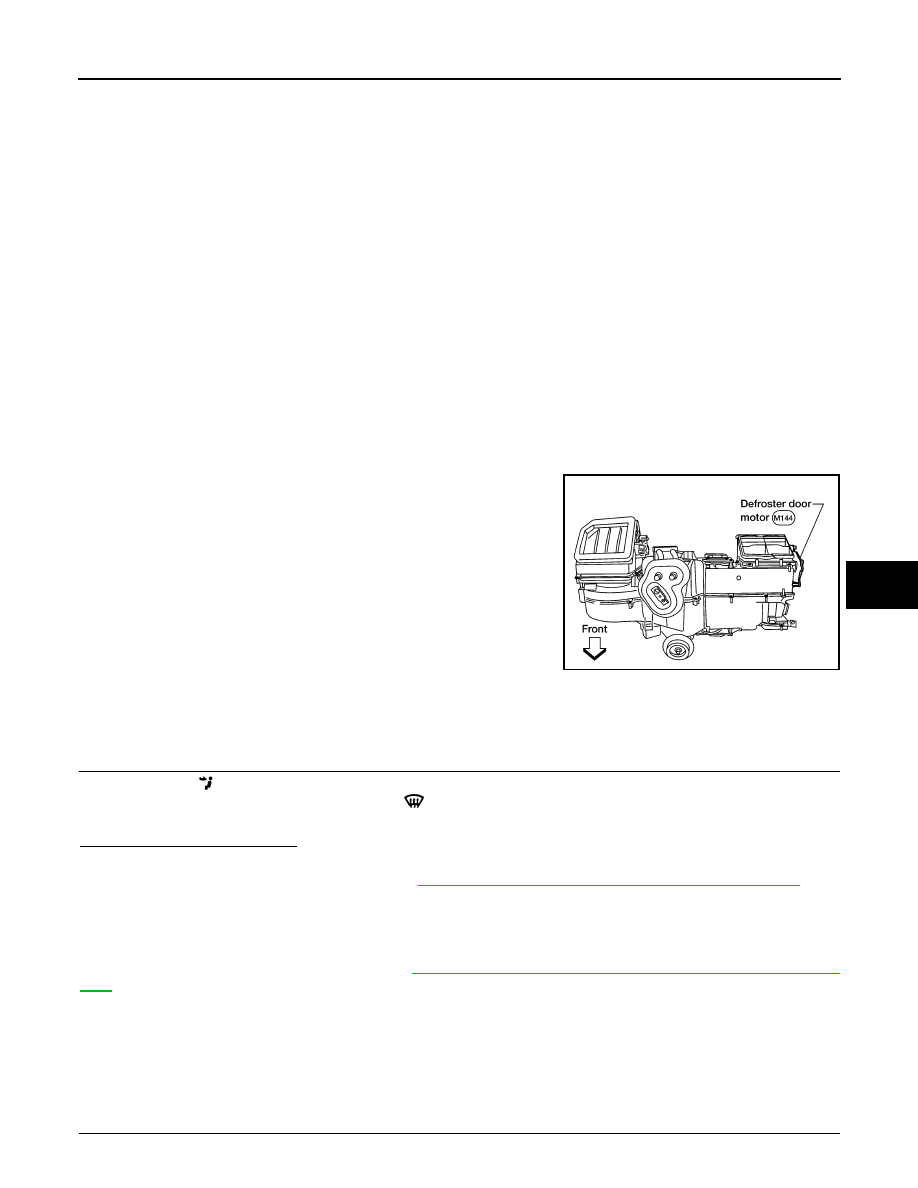
• Defroster door motor
• PBR (Built into defroster door motor)
• Intake sensor
System Operation
The front air control determines defroster door position based on the position of the defroster switch. When the
defroster switch is depressed, the defroster door motor rotates directing air to the defroster ducts. When any
mode other than defroster is selected, the defroster motor rotates in the opposite direction closing off air flow
to the defroster ducts.
COMPONENT DESCRIPTION
Defroster door motor
The defroster door motor is attached to the front heater & cooling
unit assembly. The front air control sends a voltage to rotate to the
defroster door directing the air flow either to the defroster ducts, or to
the floor ducts, depending on which way the voltage and ground are
applied to the motor leads. Motor rotation is conveyed to a lever
which activates the defroster door.
Defroster Door Motor Component Function Check
INFOID:0000000006164823
INSPECTION FLOW
1.
CONFIRM SYMPTOM BY PERFORMING OPERATIONAL CHECK - DEFROSTER DOOR
1. Select vent (
) mode.
2. Rotate mode control dial to defrost mode (
).
3. Listen for defroster door position change (blower sound should change slightly).
Is the inspection result normal?
YES
>> Inspection End.
NO
>> Go to diagnosis procedure. Refer to
HAC-207, "Defroster Door Motor Diagnosis Procedure"
.
Defroster Door Motor Diagnosis Procedure
INFOID:0000000006164824
Regarding Wiring Diagram information, refer to
HAC-232, "Wiring Diagram - Manual With 3 Control Dial Sys-
SYMPTOM:
• Defroster door does not change.
• Defroster door motor does not operate normally.
1.
CHECK DEFROSTER DOOR MOTOR CIRCUITS FOR OPEN AND SHORT TO GROUND
WJIA0592E