Nissan Titan A60. Manual - part 596


  Index      Nissan     Nissan Titan A60 (2011 year) - Service and Repair Manual


Search            


Content   ..  594  595  596  597   ..


Nissan Titan A60. Manual - part 596


POWER SUPPLY AND GROUND CIRCUIT FOR CONTROLLER

HAC-67

< DTC/CIRCUIT DIAGNOSIS >

[AUTOMATIC AIR CONDITIONER]

C

D

E

F

G

H

J

K

L

M

A

B

HAC

N

O

P

POWER SUPPLY AND GROUND CIRCUIT FOR CONTROLLER

Component Description

INFOID:0000000006164719

COMPONENT DESCRIPTION
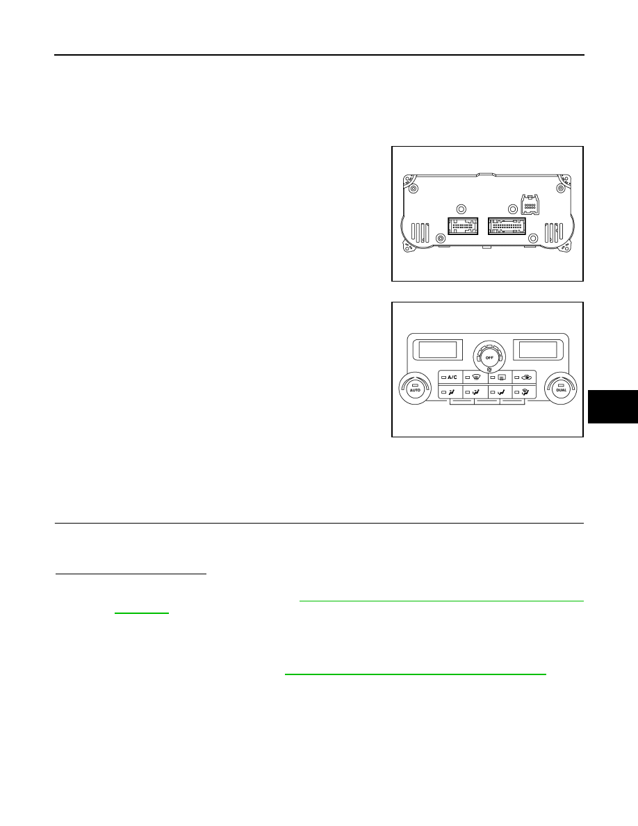
Front Air Control

The front air control has a built-in microcomputer which processes

information sent from various sensors needed for air conditioner

operation. The air mix door motors, mode door motor, intake door

motor, defroster door motor, blower motor and compressor are then

controlled.

The front air control is unitized with control mechanisms. When the

various switches and temperature dials are operated, data is input to

the front air control. 

Self-diagnostic functions are also built into the front air control to pro-

vide quick check of malfunctions in the auto air conditioner system.

Potentio Temperature Control (PTC)

There are two PTCs (driver and passenger) built into the front air

control. They can be set at an interval of 0.5

°C (1.0°F) in the 18°C

(60

°F) to 32°C (90°F) temperature range by rotating the temperature

dial. The set temperature is displayed.

Front Air Control Component Function Check

INFOID:0000000006164720

SYMPTOM: A/C system does not come on.

INSPECTION FLOW

1.

CONFIRM SYMPTOM BY PERFORMING OPERATIONAL CHECK - AUTO MODE

1. Press AUTO switch.

2. Confirm that the compressor clutch engages (sound or visual inspection). (Discharge air and blower

speed will depend on ambient, in-vehicle and set temperatures.) 

Is the inspection result normal?

YES

>> Inspection End.

NO

>> Go to diagnosis procedure. Refer to 

HAC-67, "Front Air Control Power and Ground Diagnosis

Procedure"

.

Front Air Control Power and Ground Diagnosis Procedure

INFOID:0000000006164721

Regarding Wiring Diagram information, refer to 

HAC-71, "Wiring Diagram - Automatic Air Conditioner"

.

DIAGNOSTIC PROCEDURE FOR A/C SYSTEM

AWIIA0551ZZ

AWIIA0938ZZ

HAC-68

< DTC/CIRCUIT DIAGNOSIS >

[AUTOMATIC AIR CONDITIONER]

POWER SUPPLY AND GROUND CIRCUIT FOR CONTROLLER

SYMPTOM: A/C system does not come on.

1.

 CHECK POWER SUPPLY CIRCUITS FOR FRONT AIR CONTROL

1. Turn ignition switch ON.

2. Check voltage between front air control harness connector M49

(B) terminal 15 and M50 (A) terminal 27, and ground.

Is the inspection result normal?

YES

>> GO TO 2.

NO

>> Check 10A fuses [Nos. 8 and 19, located in the fuse block (J/B)]. Refer to 

PG-73, "Terminal

Arrangement"

.

• If fuses are OK, check harness for open circuit. Repair or replace as necessary.

• If fuses are NG, replace fuse and check harness for short circuit. Repair or replace as neces-

sary.

2.

 CHECK GROUND CIRCUIT FOR FRONT AIR CONTROL

1. Turn ignition switch OFF.

2. Disconnect front air control connectors.

3. Check continuity between front air control harness connector

M50 terminal 35 and ground.

Is the inspection result normal?

OK

>> Replace front air control. Refer to 

VTL-8, "Removal and

Installation"

.

NG

>> Repair harness or connector.

AWIIA0438GB

Terminals

Ignition switch position

(+)

(-)

OFF

ACC

ON

front air 

control 

connector

Terminal No.

M49

15 

Ground

Approx. 0V

Approx. 0V

Battery 
voltage

M50

27

Battery 
voltage

Battery 
voltage

Battery 
voltage

AWIIA1073ZZ

35 - Ground

: Continuity should exist.

AWIIA0440ZZ

AIR CONDITIONER CONTROL

HAC-69

< ECU DIAGNOSIS INFORMATION >

[AUTOMATIC AIR CONDITIONER]

C

D

E

F

G

H

J

K

L

M

A

B

HAC

N

O

P

ECU DIAGNOSIS INFORMATION

AIR CONDITIONER CONTROL

Front Air Control Terminals Reference Values

INFOID:0000000006164722

Measure voltage between each terminal and ground by following

Terminals and Reference Value for front air control (1).

FRONT AIR CONTROL HARNESS CONNECTOR TERMINAL LAYOUT

TERMINALS AND REFERENCE VALUES FOR FRONT AIR CONTROL 

AWIIA0436ZZ

AWIIA0441ZZ

Terminal 

No.

Wire 

color

Item

Ignition 

switch

Condition

Voltage (V)

(Approx.)

1

G/O

Optical sensor (driver)

ON

-

0 - 5V

2

L

Air mix door motor (passenger) CCW

ON

-

Battery voltage

3

P

V ref ACTR (ground)

ON

-

 5V

4

W/R

Compressor ON signal

ON

A/C switch OFF

5V

ON

A/C switch ON

0V

5

L/R

Fan ON signal

ON

Blower switch OFF

5V

ON

Blower switch ON

0V

6

SB

Air mix door motor (driver) feedback

ON

-

0 - 5V

7

GR

Mode door motor feedback

ON

-

0 - 5V

8

R/L

Illumination +

ON

Park lamps ON

Battery voltage

9

BR

Illumination -

-

Park lamps ON

10

LG/B

Defroster door motor feedback

ON

-

0 - 5V

11

L/B

Intake sensor

ON

-

0 - 5V

13

G/R

Variable blower control

ON

-

0 - 5V

14

G/W

Air mix door motor (passenger) CW

ON

Clockwise rotation

Battery voltage

PIIA2344E

HAC-70

< ECU DIAGNOSIS INFORMATION >

[AUTOMATIC AIR CONDITIONER]

AIR CONDITIONER CONTROL

*1: If equipped

15

Y/G

Power supply for IGN

ON

-

Battery voltage

16

Y/B

Rear Defogger request *1

ON

Battery voltage

17

W/G

Air mix door motor (driver) CW

ON

Clockwise rotation

Battery voltage

18

G

Air mix door motor (driver) CCW

ON

Counterclockwise rotation

Battery voltage

19

BR/W

Mode door motor CW 

ON

Clockwise rotation

Battery voltage

20

P/L

Mode door motor CCW

ON

Counterclockwise rotation

Battery voltage

21

G/B

Intake door motor CCW

ON

Counterclockwise rotation

Battery voltage

22

O

Intake door motor CW

ON

Clockwise rotation

Battery voltage

23

LG

Defroster door motor CW

ON

Clockwise rotation

Battery voltage

24

P/B

Defroster door motor CCW

ON

 Counterclockwise rotation

Battery voltage

25

P

Ambient sensor

ON

-

0 - 5V

26

V/R

Sensor ground

ON

-

0V

27

Y/R

Power supply for BAT

-

-

Battery voltage

28

Y

V ref ACTR (5V)

ON

-

0 - 5V

29

R/W

Air mix door motor (passenger) feed-
back

ON

-

0 - 5V

31

BR/Y

In-vehicle sensor motor (+)

ON

-

Battery voltage

32

LG/R

In-vehicle sensor signal

ON

-

0 - 5V

35

B

Ground

-

-

0V

36

P

CAN-L

ON

-

0 - 5V

37

L

CAN-H

ON

-

0 - 5V

38

W/V

Optical sensor (passenger)

ON

-

0 - 5V

41

Y/L

Water valve

ON

Water valve open

Battery voltage

Water valve closed

0V

42

W/G

Water valve

ON

Water valve open

0V

Water valve closed

Battery voltage

Terminal 

No.

Wire 

color

Item

Ignition 

switch

Condition

Voltage (V)

(Approx.)


Content   ..  594  595  596  597   ..