Nissan Titan A60. Manual - part 591
BLOWER MOTOR CONTROL SYSTEM
HAC-47
< DTC/CIRCUIT DIAGNOSIS >
[AUTOMATIC AIR CONDITIONER]
C
D
E
F
G
H
J
K
L
M
A
B
HAC
N
O
P
9.
REPLACE FUSES
1. Replace fuses.
2. Activate the front blower motor.
Does the fuse blow?
YES
>> GO TO 10.
NO
>> Inspection End.
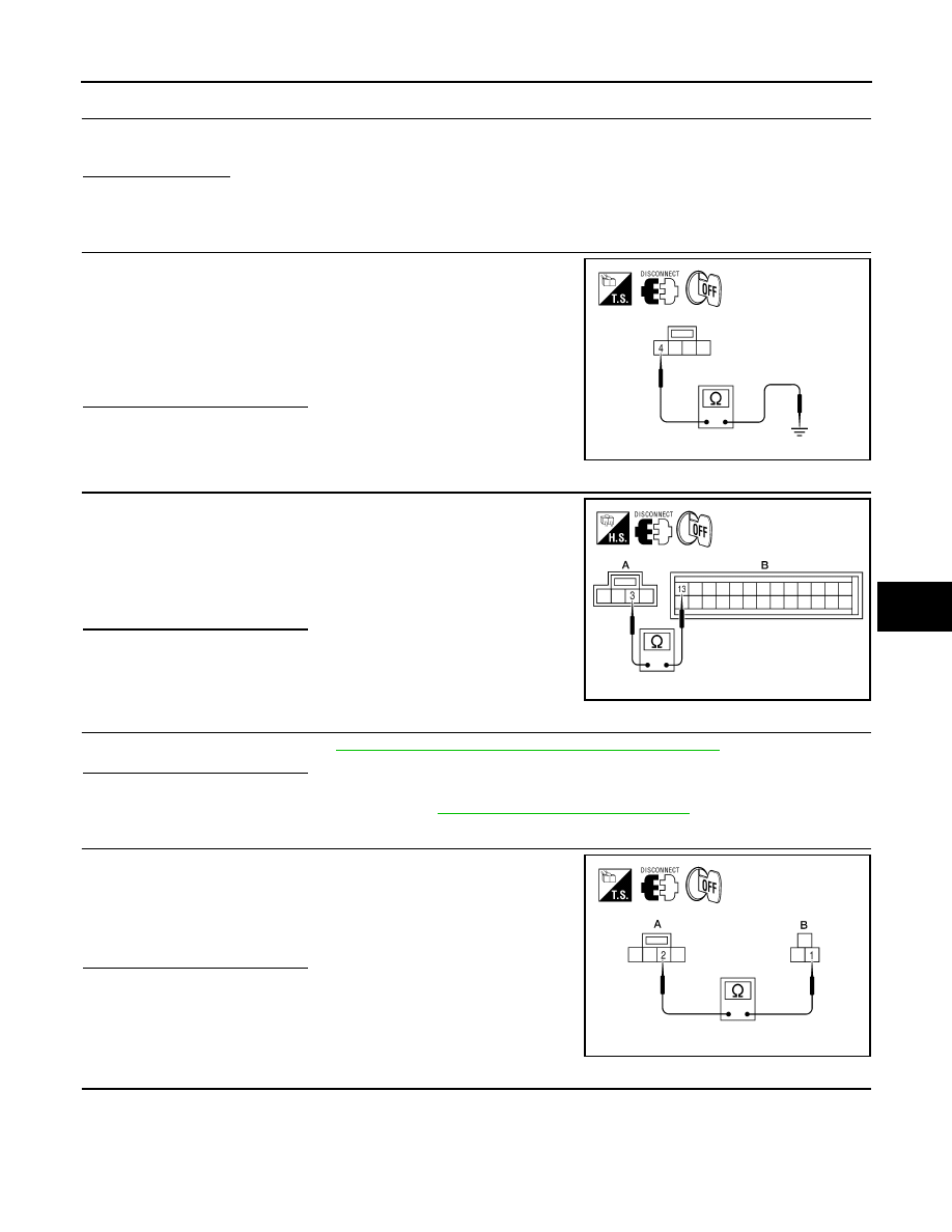
10.
CHECK FRONT BLOWER MOTOR POWER SUPPLY CIRCUIT FOR SHORT
1. Turn ignition switch OFF.
2. Disconnect front blower motor connector and variable blower
control connector.
3. Check continuity between variable blower control harness con-
nector M122 terminal 4 and ground.
Is the inspection result normal?
YES
>> GO TO 11.
NO
>> Repair harness or connector.
11.
CHECK VARIABLE BLOWER CONTROL SIGNAL CIRCUIT
1. Disconnect front air control connector.
2. Check continuity between front air control harness connector
M49 (B) terminal 13 and variable blower control harness con-
nector M122 (A) terminal 3.
Is the inspection result normal?
YES
>> GO TO 12.
NO
>> Repair harness or connector.
12.
CHECK FRONT BLOWER MOTOR
Check front blower motor. Refer to
HAC-48, "Front Blower Motor Component Inspection"
.
Is the inspection result normal?
YES
>> GO TO 13.
NO
>> Replace front blower motor. Refer to
VTL-12, "Removal and Installation"
13.
CHECK BLOWER MOTOR GROUND CIRCUIT
Check continuity between front blower motor harness connector
M62 (B) terminal 1 and variable blower control harness connector
M122 (A) terminal 2.
Is the inspection result normal?
YES
>> GO TO 14.
NO
>> Repair harness or connector.
14.
CHECK VARIABLE BLOWER CONTROL GROUND CIRCUIT
4 - Ground
: Continuity should not exist.
AWIIA0177ZZ
13 - 3
: Continuity should exist.
AWIIA0414ZZ
1 - 2
: Continuity should exist.
AWIIA0179ZZ