Nissan Titan A60. Manual - part 571
PREPARATION
HA-13
< PREPARATION >
C
D
E
F
G
H
J
K
L
M
A
B
HA
N
O
P
—
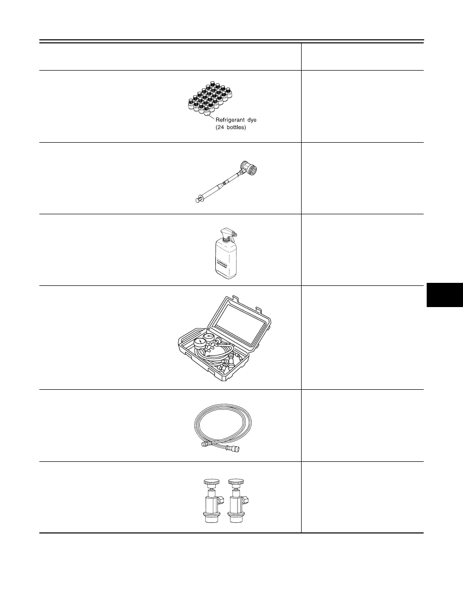
(J-41447)
HFC-134a (R-134a) Fluorescent
leak detection dye
(Box of 24, 1/4 ounce bottles)
Application: For HFC-134a (R-134a)
PAG oil
Container: 1/4 ounce (7.4cc) bottle
(Includes self-adhesive dye identifica-
tion labels for affixing to vehicle after
charging system with dye.)
—
(J-41459)
HFC-134a (R-134a) Dye injector
Use with J-41447, 1/4 ounce bottle
For injecting 1/4 ounce of fluorescent
leak detection dye into A/C system.
—
(J-43872)
Refrigerant dye cleaner
For cleaning dye spills.
—
(J-39183-C)
Manifold gauge set (with hoses
and couplers)
Identification:
• The gauge face indicates R-134a.
Fitting size-Thread size
• 1/2”-16 ACME
Service hoses:
• High side hose
(J-39500-72B)
• Low side hose
(J-39500-72R)
• Utility hose
(J-39500-72Y)
Hose color:
• Low side hose: Blue with black stripe
• High side hose: Red with black stripe
• Utility hose: Yellow with black stripe
or green with black stripe
Hose fitting to gauge:
• 1/2”-16 ACME
Service couplers
• High side coupler
(J-39500-20A)
• Low side coupler
(J-39500-24A)
Hose fitting to service hose:
• M14 x 1.5 fitting is optional or perma-
nently attached.
Tool number
(Kent-Moore No.)
Tool name
Description
SHA439F
SHA440F
SHA441F
RJIA0196E
S-NT201
S-NT202