Nissan Titan A60. Manual - part 496
HEADLAMP (HI) CIRCUIT
EXL-39
< DTC/CIRCUIT DIAGNOSIS >
C
D
E
F
G
H
I
J
K
M
A
B
EXL
N
O
P
Is the fuse open?
YES
>> Repair the harness and replace the fuse.
NO
>> GO TO 2.
2.
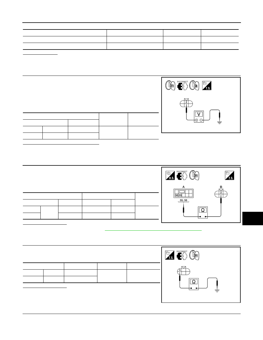
CHECK HEADLAMP (HI) OUTPUT VOLTAGE
1. Turn the ignition switch OFF.
2. Disconnect the front combination lamp connector E6 or E108.
3. Turn the ignition switch ON.
4. Turn the high beam headlamps ON.
5. With the high beam headlamps ON, check the voltage between
the combination lamp connector and ground.
Are the voltage readings as specified?
YES
>> GO TO 4.
NO
>> GO TO 3.
3.
CHECK HEADLAMP (HI) CIRCUIT FOR OPEN
1. Turn the ignition switch OFF.
2. Disconnect IPDM E/R connector E123.
3. Check continuity between the IPDM E/R harness connector (A)
and the front combination lamp harness connector (B).
Does continuity exist?
YES
>> Replace IPDM E/R. Refer to
PCS-28, "Removal and Installation of IPDM E/R"
NO
>> Repair the harnesses or connectors.
4.
CHECK FRONT COMBINATION LAMP (HI) GROUND CIRCUIT
Check continuity between the front combination lamp harness con-
nector terminal and ground.
Does continuity exist?
YES
>> Inspect the headlamp bulb.
NO (Except LH with DTRL)>>Repair the harness.
NO (LH with DTRL)>>GO TO 5.
5.
CHECK CONTINUITY BETWEEN FRONT COMBINATION LAMP LH (HI) AND DAYTIME LIGHT RELAY
1. Disconnect daytime light relay connector.
Unit
Location
Fuse No.
Capacity
Headlamp HI (LH)
IPDM E/R
35
10A
Headlamp HI (RH)
IPDM E/R
34
10A
(+)
(
−)
Voltage
Connector
Terminal
LH
E6
2
Ground
Battery voltage
RH
E108
2
ALLIA0386GB
A
B
Continuity
Connector
Terminal
Connector
Terminal
LH
E123
55
E6
2
Yes
RH
56
E108
2
ALLIA0387GB
Connector
Terminal
—
Continuity
LH
E6
3
Ground
Yes
RH
E108
3
ALLIA0388GB