Nissan Titan A60. Manual - part 480
ENGINE UNIT
EM-105
< UNIT DISASSEMBLY AND ASSEMBLY >
C
D
E
F
G
H
I
J
K
L
M
A
EM
N
P
O
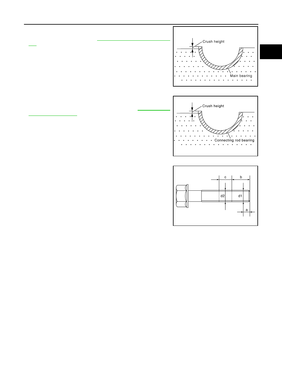
• When the bearing cap is removed after being tightened to the
specified torque with main bearings installed, the tip end of the
bearing must protrude. Refer to
EM-89, "Disassembly and Assem-
• If standard is not met, replace main bearings.
CRUSH HEIGHT OF CONNECTING ROD BEARING
• When connecting rod bearing cap is removed after being tightened
to the specified torque with the connecting rod bearings installed,
the tip end of the bearing must protrude. Refer to
for tightening procedure.
• If standard is not met, replace connecting rod bearings.
MAIN BEARING CAP BOLT DIAMETER
• Check for bolts (M9 and M12) installed from lower side using the
following procedure.
NOTE:
• Side bolt (M10) is outside the target.
• Figure shows M12 bolt.
• Measure bolt diameter
″d1″ from tip of the bolt to dimension "a".
• Measure bolt diameter
″d2″ from the dimension between tip of the
bolt and dimension
″b″ as base station to dimension ″c″.
NOTE:
If a narrower part in the threads is determined by visual check,
measure
″d2″ at that point.
• Calculate the difference between
″d1″ and ″d2″.
M9 bolt
M12 bolt
• Replace applicable bolts if outside the limit.
CONNECTING ROD BOLT DIAMETER
• Measure diameter
″d″ at position shown.
Standard
: There must be crush height
SEM502G
Standard
: There must be crush height.
PBIC1646E
KBIA2497E
Dimension “a”
: 9 mm (0.35 in)
Dimension “b”
: 15 mm (0.59 in)
Dimension “c”
: 20 mm (0.79 in)
Limit
: 0.10 mm (0.0039 in)
Dimension “a”
: 12 mm (0.47 in)
Dimension “b”
: 55 mm (2.17 in)
Dimension “c”
: 20 mm (0.79 in)
Limit
: 0.15 mm (0.0059 in)