Nissan Titan A60. Manual - part 459
CAMSHAFT VALVE CLEARANCE
EM-21
< PERIODIC MAINTENANCE >
C
D
E
F
G
H
I
J
K
L
M
A
EM
N
P
O
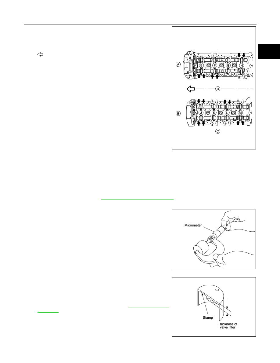
9. Turn the crankshaft pulley clockwise 90
° from the position of No.
3 cylinder compression TDC (clockwise by 360
° from the posi-
tion of No. 1 cylinder compression TDC) to measure the intake
and exhaust valve clearances of No. 6 cylinder (G) and the
exhaust valve clearance of No. 2 cylinder (E).
•
: Engine front
• A: RH
• B: LH
• C: Exhaust
• D: Intake
• E: No. 2 cylinder
• F: No. 4 cylinder
• G: No. 6 cylinder
• H: No. 8 cylinder
• J: No. 1 cylinder
• K: No. 3 cylinder
• L: No. 5 cylinder
• M: No. 7 cylinder
10. If out of specifications, adjust as necessary.
ADJUSTMENT
NOTE:
• Perform adjustment depending on the selected head thickness of the valve lifter.
• The specified valve lifter thickness is the dimension at normal temperatures. Ignore dimensional differences
caused by temperature. Use the specifications for hot engine condition to adjust.
1. Remove the camshaft. Refer to
EM-58, "Removal and Installation"
.
2. Remove the valve lifters at the locations that are out of specification.
3. Measure the center thickness of the removed valve lifters using
suitable tool.
4. Use the equation below to calculate the valve lifter thickness for
replacement.
• Valve lifter thickness calculation:
Thickness of replacement valve lifter = t1+ (C1 - C2)
t1 = Thickness of removed valve lifter
C1 = Measured valve clearance
C2= Standard valve clearance:
• Thickness of a new valve lifter can be identified by stamp
marks on the reverse side (inside the cylinder).
Stamp mark N788 indicates 7.88 mm (0.3102 in) in thickness.
• Available thickness of valve lifter: 25 sizes with range 7.88 to
8.36 mm (0.3102 to 0.3291 in) in steps of 0.02 mm (0.0008 in)
(when manufactured at factory). Refer to
5. Install the selected valve lifter.
WBIA0713E
KBIA0057E
KBIA0119E