Nissan Titan A60. Manual - part 449


  Index      Nissan     Nissan Titan A60 (2011 year) - Service and Repair Manual


Search            


Content   ..  447  448  449  450   ..


Nissan Titan A60. Manual - part 449


EC-462

< DTC/CIRCUIT DIAGNOSIS >

[VK56DE]

ON BOARD REFUELING VAPOR RECOVERY (ORVR)

a. Remove fuel gauge retainer.
b. Drain fuel from the tank using a handy pump into a fuel container.
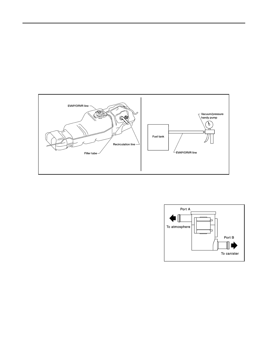
3. Check refueling EVAP vapor cut valve for being stuck to close as follows.

Blow air into the refueling EVAP vapor cut valve (from the end of EVAP/ORVR line hose), and check that

the air flows freely into the tank.

4. Check refueling EVAP vapor cut valve for being stuck to open as follows.
a. Connect vacuum pump to hose end.
b. Remove fuel gauge retainer with fuel gauge unit.

Always replace O-ring with new one.

c.

Put fuel tank upside down.

d. Apply vacuum pressure to hose end [

−13.3 kPa (−100 mmHg, −3.94 inHg)] with fuel gauge retainer

remaining open and check that the pressure is applicable.

DRAIN FILTER

1. Check visually for insect nests in the drain filter air inlet.
2. Check visually for cracks or flaws in the appearance.
3. Check visually for cracks or flaws in the hose.
4. Blow air into port A and check that it flows freely out of port B.
5. Block port B.
6. Blow air into port A and check that there is no leakage.
7. If NG, replace drain filter.

BBIA0401E

PBIB3641E

POSITIVE CRANKCASE VENTILATION

EC-463

< DTC/CIRCUIT DIAGNOSIS >

[VK56DE]

C

D

E

F

G

H

I

J

K

L

M

A

EC

N

P

O

POSITIVE CRANKCASE VENTILATION

Description

INFOID:0000000006158938

SYSTEM DESCRIPTION

This system returns blow-by gas to the intake manifold.

The positive crankcase ventilation (PCV) valve is provided to conduct crankcase blow-by gas to the intake

manifold. During partial throttle operation of the engine, the intake manifold sucks the blow-by gas through the

PCV valve. Normally, the capacity of the valve is sufficient to handle any blow-by and a small amount of venti-

lating air. The ventilating air is drawn from the air inlet tubes into the crankcase. In this process the air passes

through the hose connecting air inlet tubes to rocker cover. Under full-throttle condition, the manifold vacuum

is insufficient to draw the blow-by flow through the valve. The flow goes through the hose connection in the

reverse direction.

On vehicles with an excessively high blow-by, the valve does not

meet the requirement. This is because some of the flow will go

through the hose connection to the air inlet tubes under all condi-

tions.

Component Inspection

INFOID:0000000006158939

PCV (POSITIVE CRANKCASE VENTILATION) VALVE

With engine running at idle, remove PCV valve from rocker cover. A

properly working valve makes a hissing noise as air passes through

it. A strong vacuum should be felt immediately when a finger is

placed over valve inlet.

PCV VALVE VENTILATION HOSE

PBIB0062E

PBIB1588E

PBIB1589E

EC-464

< DTC/CIRCUIT DIAGNOSIS >

[VK56DE]

POSITIVE CRANKCASE VENTILATION

1. Check hoses and hose connections for leaks.
2. Disconnect all hoses and clean with compressed air. If any hose

cannot be freed of obstructions, replace.

S-ET277

REFRIGERANT PRESSURE SENSOR

EC-465

< DTC/CIRCUIT DIAGNOSIS >

[VK56DE]

C

D

E

F

G

H

I

J

K

L

M

A

EC

N

P

O

REFRIGERANT PRESSURE SENSOR

Component Description

INFOID:0000000006158940

The refrigerant pressure sensor is installed at the condenser of the

air conditioner system. The sensor uses an electrostatic volume

pressure transducer to convert refrigerant pressure to voltage. The

voltage signal is sent to ECM, and ECM controls cooling fan system.

Diagnosis Procedure

INFOID:0000000006158941

1.

CHECK REFRIGERANT PRESSURE SENSOR OVERALL FUNCTION

1. Start engine and warm it up to normal operating temperature.

2. Turn A/C switch and blower fan switch ON.

3. Check voltage between ECM terminal 70 and ground with CON-

SULT-III or tester.

OK or NG

OK

>> INSPECTION END

NG

>> GO TO 2.

2.

CHECK GROUND CONNECTIONS

1. Turn A/C switch and blower fan switch OFF.

2. Turn ignition switch OFF.

3. Loosen and retighten three ground screws on the body.

BBIA0356E

PBIB2657E

Voltage: 1.0 - 4.0V

PBIB1188E


Content   ..  447  448  449  450   ..