Nissan Titan A60. Manual - part 445
EC-446
< DTC/CIRCUIT DIAGNOSIS >
[VK56DE]
FUEL PUMP
FUEL PUMP
Description
INFOID:0000000006158929
SYSTEM DESCRIPTION
*: ECM determines the start signal status by the signals of engine speed and battery voltage.
The ECM activates the fuel pump for several seconds after the ignition switch is turned ON to improve engine
startability. If the ECM receives a engine speed signal from the camshaft position sensor (PHASE), it knows
that the engine is rotating, and causes the pump to operate. If the engine speed signal is not received when
the ignition switch is ON, the engine stalls. The ECM stops pump operation and prevents battery discharging,
thereby improving safety. The ECM does not directly drive the fuel pump. It controls the ON/OFF fuel pump
relay, which in turn controls the fuel pump.
COMPONENT DESCRIPTION
A turbine type design fuel pump is used in the fuel tank.
Diagnosis Procedure
INFOID:0000000006158930
EXCEPT FLEXIBLE FUEL VEHICLE
1.
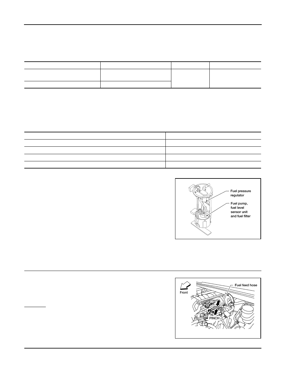
CHECK OVERALL FUNCTION
1. Turn ignition switch ON.
2. Pinch fuel feed hose with two fingers.
OK or NG
OK
>> INSPECTION END
NG
>> GO TO 2.
2.
CHECK FUEL PUMP POWER SUPPLY CIRCUIT-I
1. Turn ignition switch OFF.
Sensor
Input signal to ECM
ECM Function
Actuator
Crankshaft position sensor (POS)
Camshaft position sensor (PHASE)
Engine speed*
Fuel pump control
Fuel pump relay
Battery
Battery voltage*
Condition
Fuel pump operation
Ignition switch is turned to ON
Operates for 1 second.
Engine running and cranking
Operates.
When engine is stopped
Stops in 1.5 seconds.
Except as shown above
Stops.
BBIA0402E
Fuel pressure pulsation should be felt on the fuel feed
hose for 1 second after ignition switch is turned ON.
BBIA0357E