Nissan Titan A60. Manual - part 423
EC-358
< DTC/CIRCUIT DIAGNOSIS >
[VK56DE]
P1217 ENGINE OVER TEMPERATURE
P1217 ENGINE OVER TEMPERATURE
On Board Diagnosis Logic
INFOID:0000000006158815
If the cooling fan or another component in the cooling system malfunctions, engine coolant temperature will
rise.
When the engine coolant temperature reaches an abnormally high temperature condition, a malfunction is
indicated.
This self-diagnosis has the one trip detection logic.
CAUTION:
When a malfunction is indicated, be sure to replace the coolant. Refer to
. Also, replace the engine oil. Refer to
1. Fill radiator with coolant up to specified level with a filling speed of 2 liters per minute. Be sure to
use coolant with the proper mixture ratio. Refer to
.
2. After refilling coolant, run engine to ensure that no water-flow noise is emitted.
Overall Function Check
INFOID:0000000006158816
Use this procedure to check the overall function of the cooling fan. During this check, a DTC might not be con-
firmed.
WARNING:
Never remove the radiator cap and/or reservoir tank cap when the engine is hot. Serious burns could
be caused by high pressure fluid escaping from the radiator and/or reservoir tank.
Wrap a thick cloth around cap. Carefully remove the cap by turning it a quarter turn to allow built-up
pressure to escape. Then turn the cap all the way off.
WITH CONSULT-III
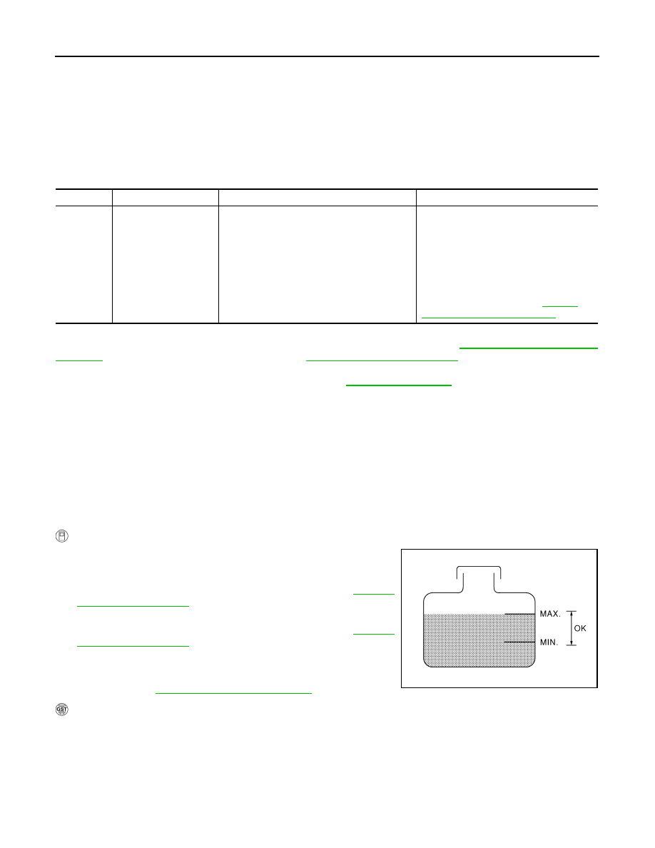
1. Check the coolant level in the reservoir tank and radiator.
Allow engine to cool before checking coolant level.
If the coolant level in the reservoir tank and/or radiator is below
the proper range, skip the following steps and go to
2. Confirm whether customer filled the coolant or not. If customer
filled the coolant, skip the following steps and go to
3. Start engine.
4. Make sure that cooling fan (crankshaft driven) operates.
5. If are NG, go to
WITH GST
DTC No.
Trouble diagnosis name
DTC detecting condition
Possible cause
P1217
1217
Engine over tempera-
ture (Overheat)
• Cooling fan does not operate properly (Over-
heat).
• Cooling fan system does not operate proper-
ly (Overheat).
• Engine coolant was not added to the system
using the proper filling method.
• Engine coolant is not within the specified
range.
• Cooling fan (crankshaft driven)
• Radiator hose
• Radiator
• Radiator cap
• Reservoir tank
• Reservoir tank cap
• Water pump
• Thermostat
For more information, refer to
"Main 13 Causes of Overheating"
SEF621W