Nissan Titan A60. Manual - part 360
EC-106
< BASIC INSPECTION >
[VK56DE]
DIAGNOSIS AND REPAIR WORKFLOW
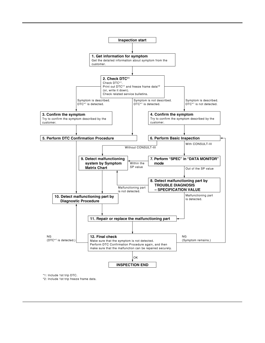
Overall Sequence
Detailed Flow
1.
GET INFORMATION FOR SYMPTOM
Get the detailed information from the customer about the symptom (the condition and the environment when
the incident/malfunction occurred) using the "DIAGNOSTIC WORKSHEET" .
>> GO TO 2.
PBIB3456E