Nissan Titan A60. Manual - part 320
P1833 INITIAL START
DLN-219
< DTC/CIRCUIT DIAGNOSIS >
[REAR FINAL DRIVE: M226 (ELD) ]
C
E
F
G
H
I
J
K
L
M
A
B
DLN
N
O
P
P1833 INITIAL START
Description
INFOID:0000000006179577
Self-diagnosis memory function was suspended due to low battery voltage at the differential lock control unit.
DTC Logic
INFOID:0000000006179578
Diagnosis Procedure
INFOID:0000000006179579
Regarding Wiring Diagram information, refer to
1.
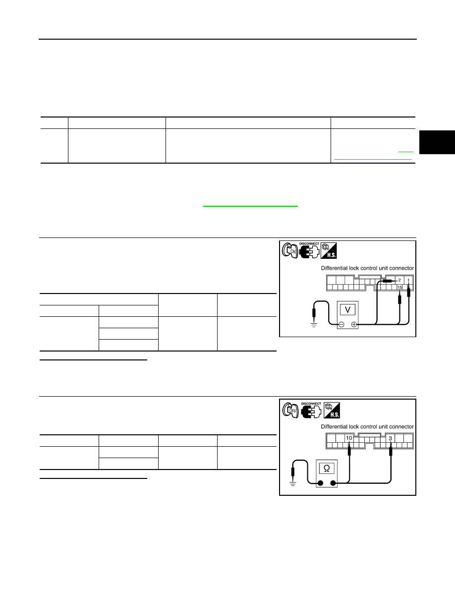
CHECK DIFFERENTIAL LOCK CONTROL UNIT POWER SUPPLY
1. Turn ignition switch OFF.
2. Disconnect differential lock control unit connector.
3. Turn ignition switch ON.
4. Check voltage between differential lock control unit connector
B77 terminals 1, 2, 15 and ground.
Is the inspection result normal?
YES
>> GO TO 2.
NO
>> Check fuse. Repair harness or connectors.
2.
CHECK DIFFERENTIAL LOCK CONTROL UNIT GROUND CIRCUIT
1. Turn ignition switch OFF.
2. Check continuity between differential lock control unit connector
B77 terminals 3, 10 and ground.
Is the inspection result normal?
YES
>> Power and ground supply is normal.
NO
>> Repair harness or connectors.
DTC
Display contents of CONSULT-III
DTC Detection Condition
Action to take
P1833
INITIAL START [P1833]
Low battery voltage available to the differential lock con-
trol unit.
Check differential lock con-
trol unit power supply and
ground circuit. Refer to
(+)
(-)
Voltage (Approx.)
Connector
Terminal
B77
1
Ground
Battery voltage
2
15
SDIA2563E
Connector
Terminal
—
Continuity
B77
3
Ground
Yes
10
SDIA2564E