Nissan Titan A60. Manual - part 312


  Index      Nissan     Nissan Titan A60 (2011 year) - Service and Repair Manual


Search            


Content   ..  310  311  312  313   ..


Nissan Titan A60. Manual - part 312


SERVICE DATA AND SPECIFICATIONS (SDS)

DLN-187

< SERVICE DATA AND SPECIFICATIONS (SDS) 

[FRONT FINAL DRIVE: M205]

C

E

F

G

H

I

J

K

L

M

A

B

DLN

N

O

P

SERVICE DATA AND SPECIFICATIONS (SDS)

SERVICE DATA AND SPECIFICATIONS (SDS)

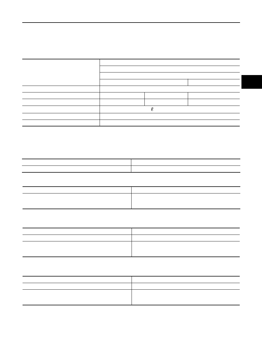
General Specification

INFOID:0000000006179550

* Option

Inspection and Adjustment

INFOID:0000000006179551

DRIVE GEAR RUNOUT

Unit: mm (in)

SIDE GEAR CLEARANCE

Unit: mm (in)

PRELOAD TORQUE

(Gear ratio :2.937 type)

Unit: N·m (kg-m, in-lb)

PRELOAD TORQUE

(Gear ratio :3.357 type)

Unit: N·m (kg-m, in-lb)

BACKLASH

Applied model

4WD

VK56DE

A/T

LE, SE, XE

Off-Road Package

Final drive model

M205

Gear ratio

2.937

3.357*

3.357

Number of teeth (Drive gear/Drive pinion)

47/16

47/14

47/14

Differential gear oil capacity (Approx.)

1.6   (3 3/8 US pt, 2 7/8 Imp pt)

Number of pinion gears

2

Drive pinion adjustment spacer type

Collapsible

Item

Limit

Drive gear back face

 0.08 (0.0031) or less

Item

Standard

Side gear back clearance (Clearance between side gear and dif-
ferential case for adjusting side gear backlash)

0.20 (0.0079) or less 

(Each gear should rotate smoothly without excessive resistance 

during differential motion.)

Item

Standard

Drive pinion bearing preload torque

2.3 - 3.4 (0.24 - 0.34, 21 - 30)

Total preload torque
(Total preload torque = drive pinion bearing preload torque + side 
bearing preload torque).

3.09 - 4.87 (0.32 - 0.49, 28 - 43)

Item

Standard

Drive pinion bearing preload torque

2.3 - 3.4 (0.24 - 0.34, 21 - 30)

Total preload torque
(Total preload torque = drive pinion bearing preload torque + side 
bearing preload torque).

2.98 - 4.76 (0.31 - 0.48, 27 - 42)

DLN-188

< SERVICE DATA AND SPECIFICATIONS (SDS) 

[FRONT FINAL DRIVE: M205]

SERVICE DATA AND SPECIFICATIONS (SDS)

Unit: mm (in)

COMPANION FLANGE RUNOUT

Unit: mm (in)

SELECTIVE PARTS

Drive Pinion Height Adjusting Washer

Unit: mm (in)

*Always check with the Parts Department for the latest parts information.

Side Gear Thrust Washer

Unit: mm (in)

*: Always check with the Parts Department for the latest parts information.

Item

Standard

Drive gear to drive pinion backlash

0.12 - 0.20 (0.0050 - 0.0078)

Item

Limit

Companion flange face

0.10 (0.0039) 

Companion flange inner side

0.13 (0.0051) 

Thickness

Package part number*

1.22 (0.048)
1.24 (0.049)
1.27 (0.050)
1.30 (0.051)
1.32 (0.052)

38154 8S111

1.35 (0.053)
1.37 (0.054)
1.40 (0.055)
1.42 (0.056)
1.45 (0.057)

38154 8S112

1.47 (0.058)
1.50 (0.059)
1.52 (0.060)
1.55 (0.061)
1.57 (0.062)

38154 8S113

1.60 (0.063)
1.63 (0.064)
1.65 (0.065)
1.68 (0.066)
1.70 (0.067)

38154 8S114

1.73 (0.068)
1.75 (0.069)
1.78 (0.070)
1.80 (0.071)
1.83 (0.072)

38154 8S115

Thickness

Package part number*

0.76 (0.030)
0.79 (0.031)
0.81 (0.032)
0.84 (0.033)
0.87 (0.034)

38424 8S111

0.89 (0.035)
0.91 (0.036)
0.94 (0.037)
0.97 (0.038)
0.99 (0.039)

38424 8S112

PRECAUTIONS

DLN-189

< PRECAUTION >

[REAR FINAL DRIVE: M226 ]

C

E

F

G

H

I

J

K

L

M

A

B

DLN

N

O

P

PRECAUTION

PRECAUTIONS

Precaution for Supplemental Restraint System (SRS) "AIR BAG" and "SEAT BELT 
PRE-TENSIONER"

INFOID:0000000006179552

The Supplemental Restraint System such as “AIR BAG” and “SEAT BELT PRE-TENSIONER”, used along

with a front seat belt, helps to reduce the risk or severity of injury to the driver and front passenger for certain

types of collision. This system includes seat belt switch inputs and dual stage front air bag modules. The SRS

system uses the seat belt switches to determine the front air bag deployment, and may only deploy one front

air bag, depending on the severity of a collision and whether the front occupants are belted or unbelted.

Information necessary to service the system safely is included in the SR and SB section of this Service Man-

ual.

WARNING:

• To avoid rendering the SRS inoperative, which could increase the risk of personal injury or death in

the event of a collision which would result in air bag inflation, all maintenance must be performed by

an authorized NISSAN/INFINITI dealer.

• Improper maintenance, including incorrect removal and installation of the SRS, can lead to personal

injury caused by unintentional activation of the system. For removal of Spiral Cable and Air Bag

Module, see the SR section.

• Do not use electrical test equipment on any circuit related to the SRS unless instructed to in this

Service Manual. SRS wiring harnesses can be identified by yellow and/or orange harnesses or har-

ness connectors.

PRECAUTIONS WHEN USING POWER TOOLS (AIR OR ELECTRIC) AND HAMMERS

WARNING:

• When working near the Airbag Diagnosis Sensor Unit or other Airbag System sensors with the Igni-

tion ON or engine running, DO NOT use air or electric power tools or strike near the sensor(s) with a

hammer. Heavy vibration could activate the sensor(s) and deploy the air bag(s), possibly causing

serious injury.

• When using air or electric power tools or hammers, always switch the Ignition OFF, disconnect the

battery, and wait at least 3 minutes before performing any service.

Precaution for Servicing Rear Final Drive

INFOID:0000000006179553

• Before starting diagnosis of the vehicle, understand the symptoms well. Perform correct and systematic

operations. 

• Check for the correct installation status prior to removal or disassembly. When matching marks are required,

be certain they do not interfere with the function of the parts they are applied to. 

• Overhaul should be done in a clean work area, a dust proof area is recommended.

• Before disassembly, completely remove sand and mud from the exterior of the unit, preventing them from

entering into the unit during disassembly or assembly.

• Always use shop paper for cleaning the inside of components.

• Avoid using cotton gloves or a shop cloth to prevent the entering of lint.

• Check appearance of the disassembled parts for damage, deformation, and abnormal wear. Replace them

with new ones if necessary. 

• Gaskets, seals and O-rings should be replaced any time the unit is disassembled.

• Clean and flush the parts sufficiently and blow them dry.

• Be careful not to damage sliding surfaces and mating surfaces.

• When applying sealant, remove the old sealant from the mating surface; then remove any moisture, oil, and

foreign materials from the application and mating surfaces.

• In principle, tighten nuts or bolts gradually in several steps working diagonally from inside to outside. If a

tightening sequence is specified, observe it.

• During assembly, observe the specified tightening torque.

• Add new differential gear oil, petroleum jelly, or multi-purpose grease, as specified.

DLN-190

< PREPARATION >

[REAR FINAL DRIVE: M226 ]

PREPARATION

PREPARATION

PREPARATION

Special Service Tool

INFOID:0000000006179554

The actual shapes of Kent-Moore tools may differ from those of special service tools illustrated here.

Tool number
(Kent-Moore No.)
Tool name

Description

ST33290001
(J-34286)
Puller

Removing front oil seal

ST15310000
(

)

Drift

Installing front oil seal
a: 96mm (3.77 in) dia.
b: 84 mm (3.30 in) dia.

ST3127S000
(J-25765-A)
Preload gauge set
1.

GG91030000
(J-25765)
Torque wrench

2.

HT62940000 (1/2

″)

(

)

Socket adapter

3.

HT62900000 (3/8

″)

(

)

Socket adapter

Inspecting drive pinion bearing preload 
torque and total preload torque

(C-4164) 
Adjuster tool

Removing and installing side bearing ad-
juster

ZZA0601D

NT115

NT124

WDIA0192E


Content   ..  310  311  312  313   ..