Nissan Titan A60. Manual - part 278
P1819 TRANSFER CONTROL DEVICE
DLN-51
< DTC/CIRCUIT DIAGNOSIS >
[TRANSFER: TX15B]
C
E
F
G
H
I
J
K
L
M
A
B
DLN
N
O
P
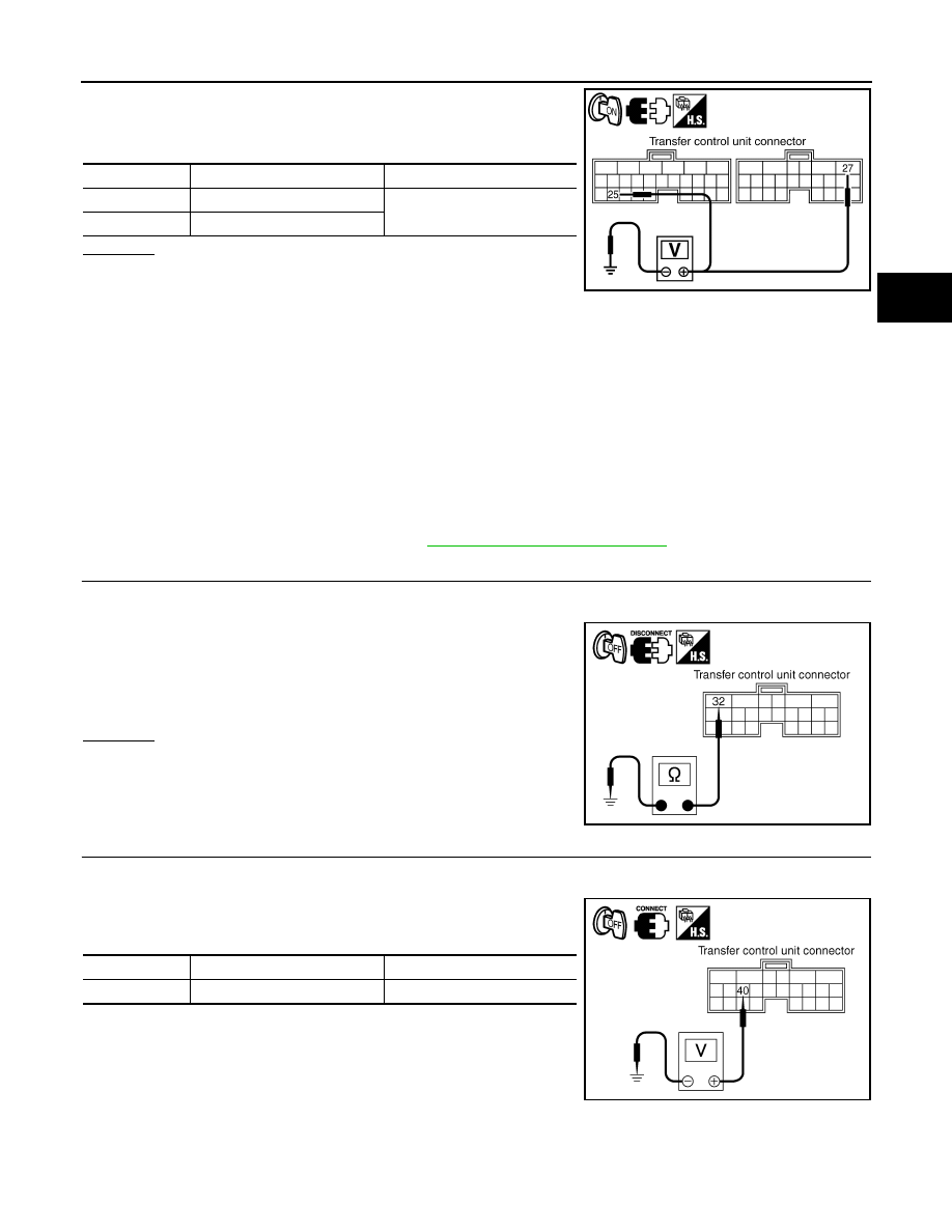
4. Turn ignition switch ON. (Do not start engine.)
5. Check voltage between transfer control unit harness connector
terminals and ground.
OK or NG
OK
>> GO TO 2.
NG
>> Check the following. If any items are damaged, repair
or replace damaged parts.
• 10A fuse (No. 59, located in the fuse and relay block).
• Harness for short or open between battery and transfer shut off relay 1 harness connector E46
terminal 5.
• Harness for short or open between transfer control unit harness connector E143 terminal 27 and
transfer shut off relay 1 harness connector E46 terminal 3.
• Harness for short or open between ignition switch and transfer shut off relay 1 harness connec-
tor E46 terminal 2.
• Harness for short or open between transfer shut off relay 1 harness connector E46 terminal 1
and ground.
• Harness for short or open between ignition switch and transfer control unit harness connector
E142 terminal 25.
• Battery and ignition switch.
• Transfer shut off relay 1. Refer to
DLN-22, "Component Inspection"
2.
CHECK GROUND CIRCUIT
1. Turn ignition switch OFF (stay for at least 5 seconds).
2. Disconnect transfer control unit harness connector.
3. Check continuity between transfer control unit harness connec-
tor E143 terminal 32 and ground.
Also check harness for short to power.
OK or NG
OK
>> GO TO 3.
NG
>> Repair open circuit or short to power in harness or con-
nectors.
3.
CHECK POWER SUPPLY SIGNAL
1. Turn ignition switch OFF. (Stay for at least 5 seconds.)
2. Connect transfer control unit harness connector.
3. Check voltage between transfer control unit harness connector
terminal and ground.
Connector
Terminal
Voltage (Approx.)
E142
25 - Ground
Battery voltage
E143
27 - Ground
SDIA3372E
Continuity should exist.
SDIA2818E
Connector
Terminal
Voltage (Approx.)
E143
40 - Ground
Battery voltage
SDIA2819E