Nissan Titan A60. Manual - part 222
REAR WINDOW DEFOGGER SWITCH
DEF-9
< DTC/CIRCUIT DIAGNOSIS >
C
D
E
F
G
H
I
J
K
M
A
B
DEF
N
O
P
DTC/CIRCUIT DIAGNOSIS
REAR WINDOW DEFOGGER SWITCH
Description
INFOID:0000000006164633
• The rear window defogger is operated by turning the rear window defogger switch ON.
• Turns the indicator lamp in the rear window defogger switch ON when operating the rear window defogger.
Component Function Check (2 Control Dial System or Auto A/C)
INFOID:0000000006164634
1.
CHECK REAR WINDOW DEFOGGER SWITCH FUNCTION
Check that the indicator lamp of rear window defogger illuminates with rear window defogger switch ON.
Is the inspection result normal?
YES
>> Rear window defogger switch function is OK.
NO
>> Refer to
DEF-9, "Diagnosis Procedure (2 Control Dial System or Auto A/C)"
Component Function Check (3 Control Dial System Without Auto A/C)
INFOID:0000000006164635
1.
CHECK REAR WINDOW DEFOGGER SWITCH FUNCTION
Check that the indicator lamp of rear window defogger illuminates with rear window defogger switch ON.
Is the inspection result normal?
YES
>> Rear window defogger switch function is OK.
NO
>> Refer to
DEF-10, "Diagnosis Procedure (3 Control Dial System Without Auto A/C)"
Diagnosis Procedure (2 Control Dial System or Auto A/C)
INFOID:0000000006164636
Regarding Wiring Diagram information, refer to
.
1.
CHECK FRONT AIR CONTROL (REAR WINDOW DEFOGGER SWITCH) CIRCUIT
Operate the rear window defogger switch.
Is the inspection result normal?
YES
>> Inspection End.
NO
>> GO TO 2
2.
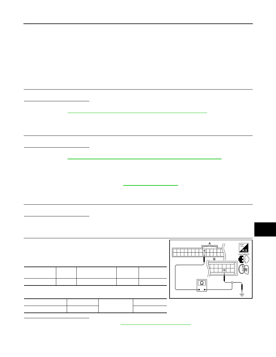
CHECK HARNESS CONTINUITY
1. Turn ignition switch OFF.
2. Disconnect BCM and front air control.
3. Check continuity between BCM connector (A) and front air con-
trol connector (B).
4. Check continuity between BCM connector (A) and ground.
Is the inspection result normal?
YES
>> Replace front air control. Refer to
VTL-8, "Removal and Installation"
.
NO
>> Repair or replace harness.
BCM connector
Terminal
Front air control con-
nector
Terminal
Continuity
M18 (A)
9
M49 or M180 (B)
16
Yes
BCM connector
Terminal
Ground
Continuity
M18 (A)
9
No
ALLIA0561ZZ