Nissan Titan A60. Manual - part 198


  Index      Nissan     Nissan Titan A60 (2011 year) - Service and Repair Manual


Search            


Content   ..  196  197  198  199   ..


Nissan Titan A60. Manual - part 198


REPAIRING HIGH STRENGTH STEEL

BRM-51

< UNIT REMOVAL AND INSTALLATION >

C

D

E

F

G

H

I

J

L

M

A

B

BRM

N

O

P

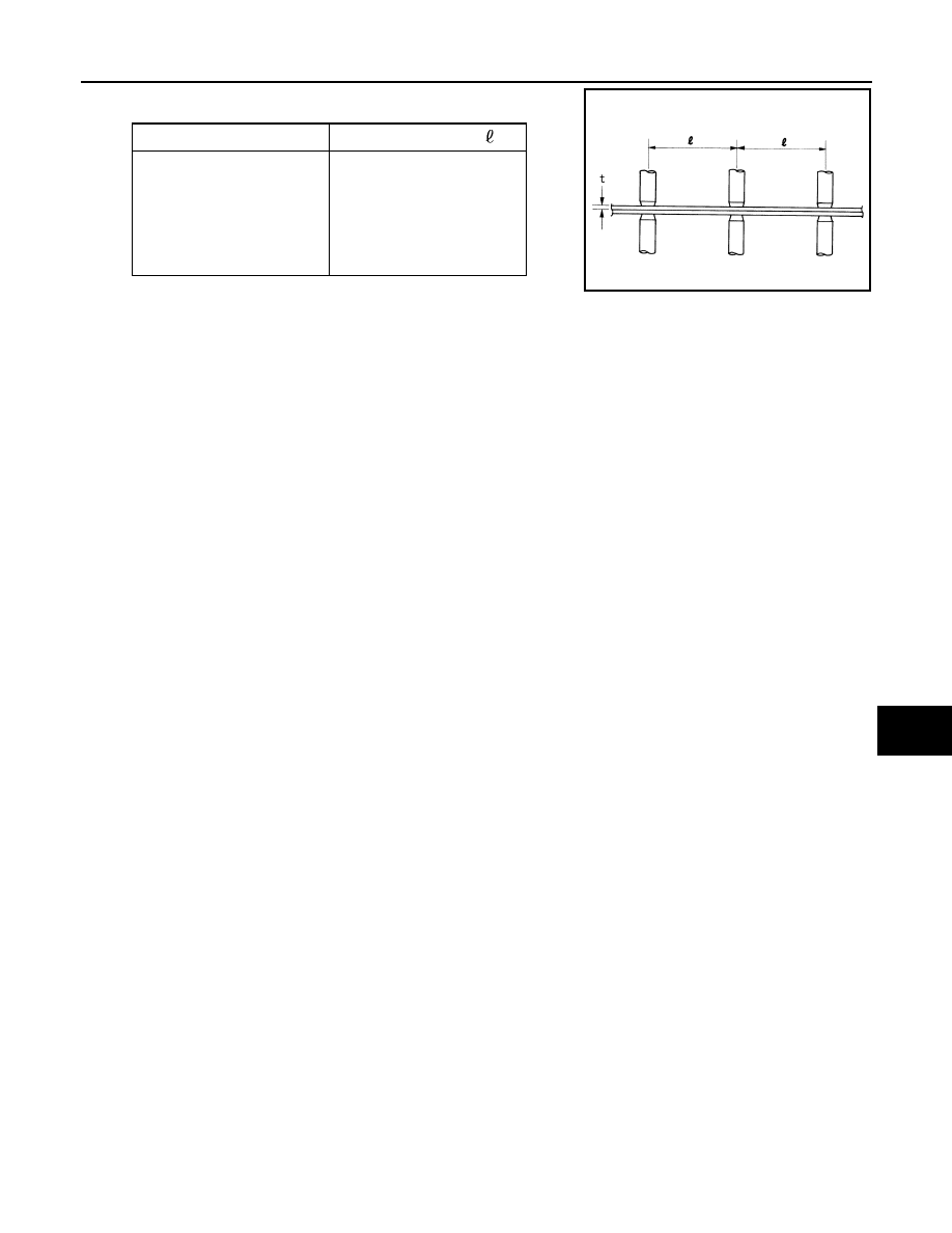
• Follow the specifications for the proper welding pitch.

Unit:mm

Thickness (t)

Minimum pitch ( )

0.6 (0.024)
0.8 (0.031)
1.0 (0.039)
1.2 (0.047)
1.6 (0.063)
1.8 (0.071)

10 (0.39) or over
12 (0.47) or over
18 (0.71) or over
20 (0.79) or over
27 (1.06) or over
31 (1.22) or over

PIIA0148E

BRM-52

< UNIT REMOVAL AND INSTALLATION >

REPLACEMENT OPERATIONS

REPLACEMENT OPERATIONS

Replacement Operation

INFOID:0000000006158474

DESCRIPTION

This section is prepared for technicians who have attained a high level of skill and experience in repairing col-

lision-damaged vehicles and also use modern service tools and equipment. Persons unfamiliar with body

repair techniques should not attempt to repair collision-damaged vehicles by using this section.

Technicians are also encouraged to read Body Repair Manual (Fundamentals) in order to ensure that the orig-

inal functions and quality of the vehicle can be maintained. The Body Repair Manual (Fundamentals) contains

additional information, including cautions and warnings, that are not including in this manual. Technicians

should refer to both manuals to ensure proper repairs.

Please note that this information is prepared for worldwide usage, and as such, certain procedures may not

apply in some regions or countries.

REPLACEMENT OPERATIONS

BRM-53

< UNIT REMOVAL AND INSTALLATION >

C

D

E

F

G

H

I

J

L

M

A

B

BRM

N

O

P

The symbols used in this section for cutting and welding / brazing operations are shown below.

PIIA0149E

BRM-54

< UNIT REMOVAL AND INSTALLATION >

REPLACEMENT OPERATIONS

• Front pillar butt joint can be determined anywhere within shaded

area as shown in the figure. The best location for the butt joint is at

position A due to the construction of the vehicle. Refer to the front

pillar section.

• Determine cutting position and record distance from the locating

indent. Use this distance when cutting the service part. Cut outer

front pillar over 60 mm above inner front pillar cut position.

• Prepare a cutting jig to make outer pillar easier to cut. Also, this will

permit service part to be accurately cut at joint position.

• An example of cutting operation using a cutting jig is as follows.

1. Mark cutting lines.

A: Cut position of outer pillar

B: Cut position of inner pillar

2. Align cutting line with notch on jig. Clamp jig to pillar.

3. Cut outer pillar along groove of jig. (At position A)

4. Remove jig and cut remaining portions.

5. Cut inner pillar at position B in same manner.

HOODLEDGE

• Work after radiator core support has been removed.

PIIA0150E

PIIA0151E

PIIA0152E

PIIA0153E


Content   ..  196  197  198  199   ..