Nissan Titan A60. Manual - part 169


  Index      Nissan     Nissan Titan A60 (2011 year) - Service and Repair Manual


Search            


Content   ..  167  168  169  170   ..


Nissan Titan A60. Manual - part 169


BRC-54

< DTC/CIRCUIT DIAGNOSIS >

[VDC/TCS/ABS]

C1140 ACTUATOR RLY

C1140 ACTUATOR RLY

Description

INFOID:0000000006165878

Activates or deactivates each solenoid valve according to the signals transmitted by the ABS actuator and

electric unit (control unit). 

DTC Logic

INFOID:0000000006165879

DTC DETECTION LOGIC

DTC CONFIRMATION PROCEDURE

1.

CHECK SELF-DIAGNOSIS RESULTS

Check the self-diagnosis results.

Is above displayed on the self-diagnosis display?

YES

>> Proceed to diagnosis procedure. Refer to 

BRC-54, "Diagnosis Procedure"

.

NO

>> Inspection End

Diagnosis Procedure

INFOID:0000000006648994

Regarding Wiring Diagram information, refer to 

BRC-92, "Wiring Diagram"

.

1.

CONNECTOR INSPECTION

1. Turn ignition switch OFF.

2. Disconnect ABS actuator and electric unit (control unit) connector.

3. Check terminals for deformation, disconnection, looseness, and so on. If any malfunction is found, repair

or replace terminals.

4. Reconnect connectors and then perform the self-diagnosis. Refer to 

BRC-24, "CONSULT-III Function

(ABS)"

.

Is any item indicated on the self-diagnosis display?

YES

>> GO TO 2

NO

>> Poor connection of connector terminals. Repair or replace connector.
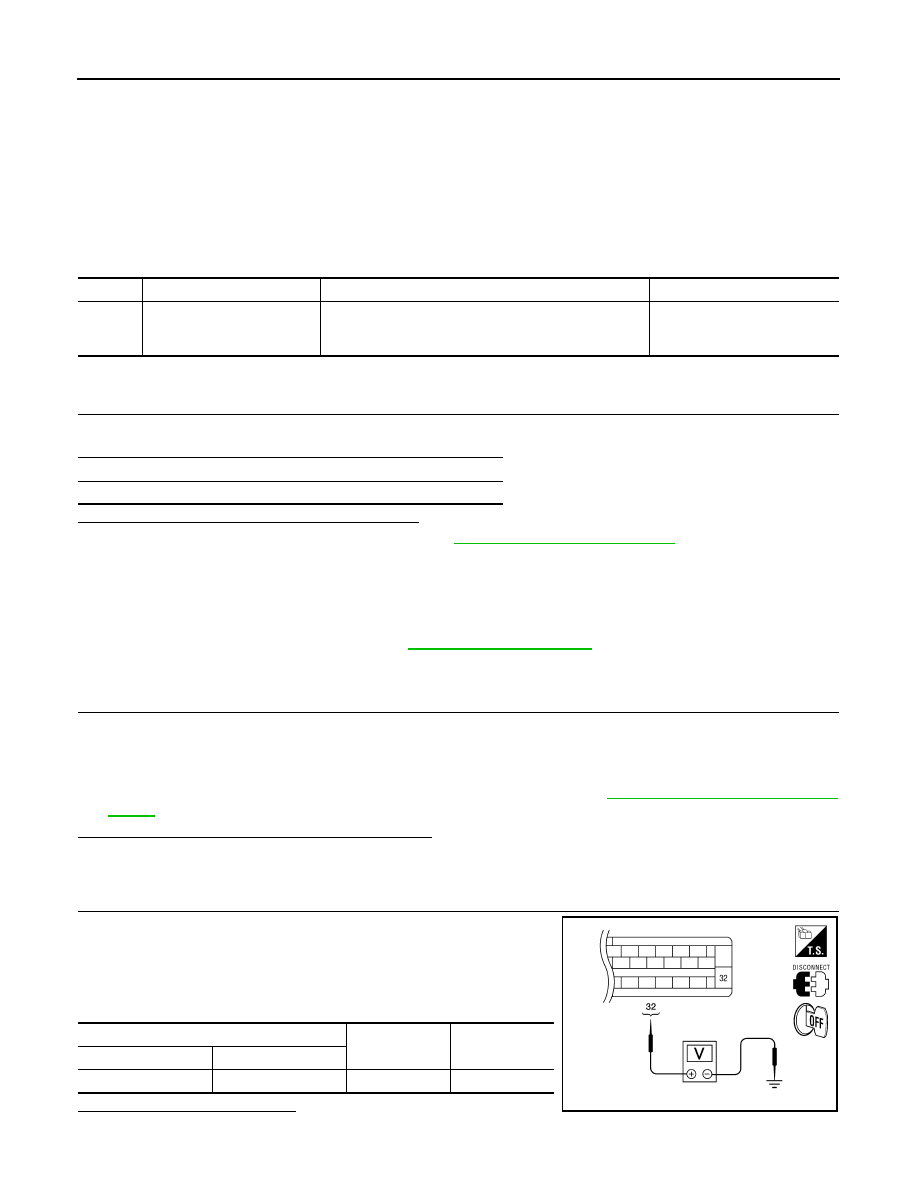
2.

CHECK SOLENOID, VDC SWITCH-OVER VALVE AND ACTUATOR RELAY POWER SUPPLY CIRCUIT

1. Turn ignition switch OFF.

2. Disconnect ABS actuator and electric unit (control unit) connec-

tor.

3. Check voltage between ABS actuator and electric unit (control

unit) connector E125 terminal 32 and ground.

Is the inspection result normal?

YES

>> GO TO 3

DTC

Display item

Malfunction detected condition

Possible cause

C1140

ACTUATOR RLY

ABS actuator relay or circuit malfunction.

• Harness or connector
• ABS actuator and electric unit 

(control unit)

Self-diagnosis results

ACTUATOR RLY

ABS actuator and electric unit (control unit)

Voltage

Connector

Terminal

E125

32

Ground

Battery voltage

AWFIA0018ZZ

C1140 ACTUATOR RLY

BRC-55

< DTC/CIRCUIT DIAGNOSIS >

[VDC/TCS/ABS]

C

D

E

G

H

I

J

K

L

M

A

B

BRC

N

O

P

NO

>> Repair or replace malfunctioning components.

3.

CHECK SOLENOID, VDC SWITCH-OVER VALVE AND ACTUATOR RELAY GROUND CIRCUIT

Check continuity between ABS actuator and electric unit (control

unit) connector E125 terminals 16, 47 and ground.

Is the inspection result normal?

YES

>> Replace ABS actuator and electric unit (control unit).

Refer to 

BRC-116, "Removal and Installation"

.

NO

>> Repair or replace malfunctioning components.

Component Inspection

INFOID:0000000006648995

1.

CHECK ACTIVE TEST

1. On “ACTIVE TEST”, select “ABS MOTOR”.

2. Touch On and Off on screen. Make sure motor relay and actuator relay operates as shown in table below.

Is the inspection result normal?

YES

>> Inspection End

NO

>> Go to diagnosis procedure. Refer to 

BRC-38, "Diagnosis Procedure"

.

Special Repair Requirement

INFOID:0000000006648996

1.

ADJUSTMENT OF STEERING ANGLE SENSOR NEUTRAL POSITION

Always perform neutral position adjustment for the steering angle sensor when replacing the ABS actuator

and electric unit (control unit). Refer to 

BRC-8, "ADJUSTMENT OF STEERING ANGLE SENSOR NEUTRAL

POSITION : Description"

.

>> GO TO 2

2.

CALIBRATION OF DECEL G SENSOR

Always perform calibration of decel G sensor when replacing the ABS actuator and electric unit (control unit).

Refer to 

BRC-9, "CALIBRATION OF DECEL G SENSOR : Description"

.

>> END

ABS actuator and electric unit (control unit)

Continuity

Connector

Terminal

E125

16, 47

Ground

Yes

AWFIA0016ZZ

Operation

On

Off

MOTOR RELAY

On

Off

ACTUATOR RLY

On

On

BRC-56

< DTC/CIRCUIT DIAGNOSIS >

[VDC/TCS/ABS]

C1142 PRESS SENSOR

C1142 PRESS SENSOR

Description

INFOID:0000000006165883

The front and rear pressure sensors convert the brake fluid pressure to an electric signal and transmit it to the

ABS actuator and electric unit (control unit).

DTC Logic

INFOID:0000000006165884

DTC DETECTION LOGIC

DTC CONFIRMATION PROCEDURE

1.

CHECK SELF-DIAGNOSIS RESULTS

Check the self-diagnosis results.

Is above displayed on the self-diagnosis display?

YES

>> Proceed to diagnosis procedure. Refer to 

BRC-56, "Diagnosis Procedure (Front Pressure Sen-

sor)"

 or 

BRC-57, "Diagnosis Procedure (Rear Pressure Sensor)"

.

NO

>> Inspection End

Diagnosis Procedure (Front Pressure Sensor)

INFOID:0000000006165885

Regarding Wiring Diagram information, refer to 

BRC-92, "Wiring Diagram"

.

1.

CONNECTOR INSPECTION

1. Turn the ignition switch OFF.

2. Disconnect the front pressure sensor and ABS actuator and electric unit (control unit) connectors.

3. Inspect the terminals for deformation, disconnection, looseness, or damage.
Is the inspection result normal?

YES

>> GO TO 2

NO

>> Repair connector.

2.

FRONT PRESSURE SENSOR CIRCUIT INSPECTION

1. Measure the continuity between the ABS actuator and electric

unit (control unit) connector E125 (A) and front pressure sensor

connector E31 (B).

2. Measure the continuity between the ABS actuator and electric unit (control unit) connector E125 (A) and

body ground.

DTC

Display item

Malfunction detected condition

Possible cause

C1142

PRESS SEN CIRCUIT

Pressure sensor signal line is open or shorted, or pres-
sure sensor is malfunctioning.

• Harness or connector
• Pressure sensor
• ABS actuator and electric unit 

(control unit)

Self-diagnosis results

PRESS SEN CIRCUIT

ABS actuator and electric unit 

(control unit)

Front pressure sensor

Continuity

Connector

Terminal

Connector

Terminal

A: E125

18

B: E31

3

Yes

19

1

20

2

AWFIA0021ZZ

C1142 PRESS SENSOR

BRC-57

< DTC/CIRCUIT DIAGNOSIS >

[VDC/TCS/ABS]

C

D

E

G

H

I

J

K

L

M

A

B

BRC

N

O

P

Is the inspection result normal?

YES

>> GO TO 3

NO

>> Repair or replace harness or connector.

3.

FRONT PRESSURE SENSOR INSPECTION

1. Reconnect the front pressure sensor and ABS actuator and electric unit (control unit) connectors.

2. Perform the “PRESS SENSOR” component inspection. Refer to 

BRC-58, "Component Inspection (Front

Pressure Sensor)"

.

Is the inspection result normal?

YES

>> Inspection End.

NO

>> Replace the front pressure sensor.

Diagnosis Procedure (Rear Pressure Sensor)

INFOID:0000000006649013

Regarding Wiring Diagram information, refer to 

BRC-92, "Wiring Diagram"

.

1.

CONNECTOR INSPECTION

1. Turn the ignition switch OFF.

2. Disconnect the rear pressure sensor and ABS actuator and electric unit (control unit) connectors.

3. Inspect the terminals for deformation, disconnection, looseness, or damage.
Is the inspection result normal?

YES

>> GO TO 2

NO

>> Repair connector.

2.

REAR PRESSURE SENSOR CIRCUIT INSPECTION

1. Measure the continuity between the ABS actuator and electric

unit (control unit) connector E125 (A) and rear pressure sensor

connector E32 (B).

2. Measure the continuity between the ABS actuator and electric unit (control unit) connector E125 (A) and

body ground.

ABS actuator and electric unit (control 

unit)

Continuity

Connector

Terminal

A: E125

18

Ground

No

19

20

ABS actuator and electric unit 

(control unit)

Rear pressure sensor

Continuity

Connector

Terminal

Connector

Terminal

A: E125

21

B: E32

1

Yes

22

3

23

2

ABS actuator and electric unit (control 

unit)

Continuity

Connector

Terminal

A: E125

21

Ground

No

22

23

AWFIA0022ZZ


Content   ..  167  168  169  170   ..