Nissan Titan A60. Manual - part 164
BRC-34
< DTC/CIRCUIT DIAGNOSIS >
[VDC/TCS/ABS]
C1105, C1106, C1107, C1108 WHEEL SENSOR-2
Is the inspection result normal?
YES
>> Replace the ABS actuator and electric unit (control unit). Refer to
.
NO
>> Repair the circuit.
Component Inspection
INFOID:0000000006648980
1.
CHECK DATA MONITOR
On “DATA MONITOR”, select “FR LH SENSOR”, “FR RH SENSOR”, “RR LH SENSOR”, and “RR RH SEN-
SOR”, and check the vehicle speed.
Is the inspection result normal?
YES
>> Inspection End
NO
>> Go to diagnosis procedure. Refer to
Special Repair Requirement
INFOID:0000000006648981
1.
ADJUSTMENT OF STEERING ANGLE SENSOR NEUTRAL POSITION
Always perform neutral position adjustment for the steering angle sensor when replacing the ABS actuator
and electric unit (control unit). Refer to
BRC-8, "ADJUSTMENT OF STEERING ANGLE SENSOR NEUTRAL
.
>> GO TO 2
2.
CALIBRATION OF DECEL G SENSOR
Always perform calibration of decel G sensor when replacing the ABS actuator and electric unit (control unit).
BRC-9, "CALIBRATION OF DECEL G SENSOR : Description"
>> END
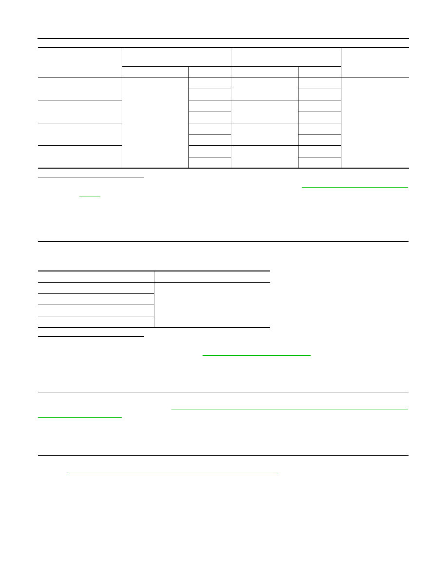
Wheel sensor
ABS actuator and
electric unit (control unit)
Wheel sensor
Continuity
Connector
Terminal
Connector
Terminal
Front LH
E125
45
E18
1
Yes
46
2
Front RH
34
E117
1
33
2
Rear LH
37
C11
2
36
1
Rear RH
42
C10
2
43
1
Wheel sensor
Vehicle speed (DATA MONITOR)
FR LH SENSOR
Nearly matches the speedometer dis-
play (
±10% or less)
FR RH SENSOR
RR LH SENSOR
RR RH SENSOR