Nissan Titan A60. Manual - part 155
SERVICE DATA AND SPECIFICATIONS (SDS)
BR-47
< SERVICE DATA AND SPECIFICATIONS (SDS)
C
D
E
G
H
I
J
K
L
M
A
B
BR
N
O
P
SERVICE DATA AND SPECIFICATIONS (SDS)
SERVICE DATA AND SPECIFICATIONS (SDS)
General Specification
INFOID:0000000006163306
Unit: mm (in)
Brake Pedal
INFOID:0000000006163307
STANDARD PEDAL
Unit: mm (in)
Front brake
Brake model
AD41VA
Rotor outer diameter
× thickness
350
× 30 (13.78 × 1.181)
Pad Length
× width × thickness
151.6
× 56.5 × 12.0 (5.97 × 2.22 × 0.472)
Cylinder bore diameter (each)
50.8 (2.00)
Rear brake
Brake model
AD14VE
Rotor outer diameter
× thickness
320
× 14 (12.6 × 0.551)
Pad Length
× width × thickness
83.0
× 33.0 × 12.0 (3.268 × 1.299 × 0.472)
Cylinder bore diameter
48 (1.89)
Control valve
Valve model
Electric brake force distribution
Brake booster
Booster model
C215T
Diaphragm diameter
215 (8.46)
Recommended brake fluid
MA-21, "FOR NORTH AMERICA : Fluids and Lubri-
(Mexico).
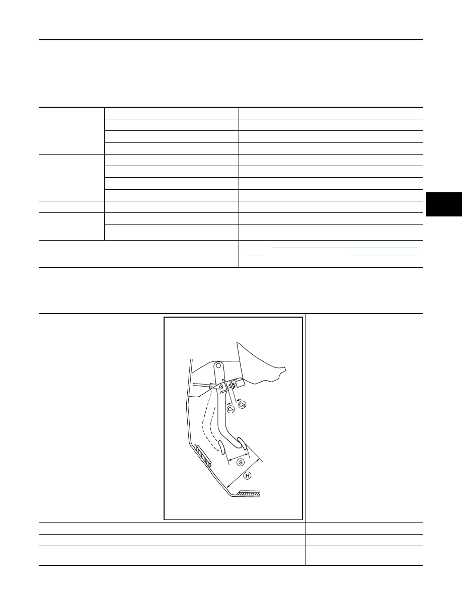
Free height (H)
182.3
− 192.3 (7.18 − 7.57)
Pedal full stroke (S)
152.3 (6.00)
Clearance between brake pedal bracket and the threaded end of stop lamp switch (C1) and
ASCD cancel switch [if equipped] (C
2
)
0.74
− 1.96 (0.029 − 0.077)
AWFIA0557ZZ