Nissan Titan A60. Manual - part 110


  Index      Nissan     Nissan Titan A60 (2011 year) - Service and Repair Manual


Search            


Content   ..  108  109  110  111   ..


Nissan Titan A60. Manual - part 110


AV

MICROPHONE SIGNAL CIRCUIT

AV-265

< DTC/CIRCUIT DIAGNOSIS >

[PREMIUM WITH NAVIGATION]

C

D

E

F

G

H

I

J

K

L

M

B

A

O

P

MICROPHONE SIGNAL CIRCUIT

Description

INFOID:0000000006166620

Voice signals are transmitted from the microphone to the Bluetooth control unit using the microphone signal

circuits.

Diagnosis Procedure

INFOID:0000000006166621

Regarding Wiring Diagram information, refer to 

AV-285, "Wiring Diagram - With Navigation System"

.

1.

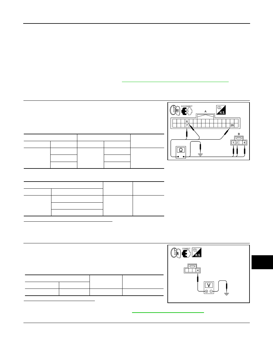
CHECK HARNESS BETWEEN BLUETOOTH CONTROL UNIT AND MICROPHONE

1. Turn ignition switch OFF.

2. Disconnect Bluetooth control unit connector and microphone

connector.

3. Check continuity between Bluetooth control unit harness con-

nector B142 (A) and microphone harness connector R109 (B).

4. Check continuity between Bluetooth control unit harness connector B142 (A) and ground.

Are the continuity test results as specified?

YES

>> GO TO 2.

NO

>> Repair harness or connector.

2.

CHECK MICROPHONE POWER SUPPLY

1. Connect Bluetooth control unit connector and microphone con-

nector.

2. Turn ignition switch ON.

3. Check voltage between microphone harness connector R109

terminal 4 and ground.

Is voltage reading approx. 5 volts?

YES

>> GO TO 3.

NO

>> Replace Bluetooth control unit. Refer to 

AV-343, "Removal and Installation"

.

3.

CHECK MICROPHONE SIGNAL

A

B

Continuity

Connector

Terminal

Connector

Terminal

B142

7

R109

1

Yes

8

2

29

4

A

Continuity

Connector

Terminal

B142

7

Ground

No

8

29

WKIA5795E

(+)

(-)

Voltage (approx.)

Connector

Terminal

R109

4

Ground

5V

WKIA5796E

AV-266

< DTC/CIRCUIT DIAGNOSIS >

[PREMIUM WITH NAVIGATION]

MICROPHONE SIGNAL CIRCUIT

Check signal between Bluetooth control unit harness connector

B142 terminals 7 and 8 with CONSULT-III or and oscilloscope.

Are voltage readings as specified?

YES

>> Replace Bluetooth control unit. Refer to 

AV-343, "Removal and Installation"

.

NO

>> Replace microphone. Refer to 

AV-341, "Removal and Installation"

.

Connector

(+)

(-)

Reference signal

Terminal

Terminal

B142

7

8

While speaking into MIC

AWNIA1620ZZ

PKIB5037J

AV

AUDIO UNIT

AV-267

< ECU DIAGNOSIS INFORMATION >

[PREMIUM WITH NAVIGATION]

C

D

E

F

G

H

I

J

K

L

M

B

A

O

P

ECU DIAGNOSIS INFORMATION

AUDIO UNIT

Reference Value

INFOID:0000000006166622

TERMINAL LAYOUT

PHYSICAL VALUES

ALNIA0712GB

Terminal

 (Wire color)

Item

Signal 

input/

output

Condition

Reference value

(Approx.)

+

(W)

(B)

Audio sound signal 
front LH

Output

Ignition 

switch 

ON

Receive audio sig-
nal

(Y)

(BR)

Audio sound signal 
front RH

Output

Ignition 

switch 

ON

Receive audio sig-
nal

(Y)

Ground

Battery power

Input

Battery voltage

(BR)

Ground

Illumination control 
signal

Input

Ignition 

switch 

ON

Illumination control 
switch is operated 
by lighting switch in 
1st position.

Changes between 0 and 12V

(R/L)

Ground

Illumination signal

Input

OFF

Lighting switch is in 
1st position.

Battery voltage

Lighting switch is 
OFF.

0V

9

Shield

0V

10 

(V)

Ground

ACC signal

Input

Ignition 

switch 

ON

Battery voltage

12

(G/W)

Ground

Amp ON

Input

Ignition 

switch 

ON

Audio unit ON

More than 6.5V

SKIA0177E

SKIA0177E

AV-268

< ECU DIAGNOSIS INFORMATION >

[PREMIUM WITH NAVIGATION]

AUDIO UNIT

14 

(BR)

13 

(B/R)

Audio sound signal 
rear LH

Output

Ignition 

switch 

ON

Receive audio sig-
nal

16 

(L)

15 

(B/W)

Audio sound signal 
rear RH

Output

Ignition 

switch 

ON

Receive audio sig-
nal

21

 (V)

Ground

Remote control A

Output

Ignition 

switch 

ON

Audio unit ON

5V

22 

(P)

Ground

Remote control B

Output

Ignition 

switch 

ON

Audio unit ON

5V

23 

(BR/Y)

Ground

Remote control C

Output

Ignition 

switch 

ON

Audio unit ON

5V

24 

(L)

Ground

Remote control D

Output

Ignition 

switch 

ON

Audio unit ON

5V

25 

(LG) 

Ground

Remote control 
ground

0V

27 

(O/L)

26 

(O)

Audio sound signal 
LH

Output

Ignition 

switch 

ON

Receive audio sig-
nal

29 

(W)

28 

(W/L)

Audio sound signal 
RH

Output

Ignition 

switch 

ON

Receive audio sig-
nal

30 –

Shield

0V

31

(O)

Ground

Remote control en-
able signal

Output

Ignition 

switch 

ON

Audio unit ON

5V

32 

(V)

Ground

Remote control 
switch power sup-
ply

Output

Ignition 

switch 

ON

Audio unit ON

12V

Terminal

 (Wire color)

Item

Signal 

input/

output

Condition

Reference value

(Approx.)

+

SKIA0177E

SKIA0177E

SKIA0177E

SKIA0177E


Content   ..  108  109  110  111   ..