Content .. 1008 1009 1010 1011 ..
Nissan Titan A60. Manual - part 1010
FRONT WIPER AUTO STOP SIGNAL CIRCUIT
WW-19
< DTC/CIRCUIT DIAGNOSIS >
C
D
E
F
G
H
I
J
K
M
A
B
WW
N
O
P
FRONT WIPER AUTO STOP SIGNAL CIRCUIT
Component Function Check
INFOID:0000000006164531
1.
CHECK FRONT WIPER (AUTO STOP) SIGNAL
CONSULT-III DATA MONITOR
1. Select "FR WIPER STOP" of IPDM E/R data monitor item.
2. Operate the front wiper.
3. Check that "FR WIPER STOP" changes to "ON" and "OFF" linked with the wiper operation.
Is the status of item normal?
YES
>> Front wiper auto stop signal circuit is normal.
NO
>> Refer to
.
Diagnosis Procedure
INFOID:0000000006164532
Regarding Wiring Diagram information, refer to
.
1.
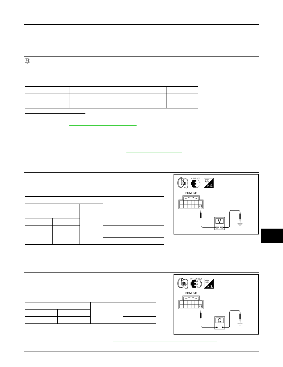
CHECK FRONT WIPER MOTOR (AUTO STOP) OUTPUT VOLTAGE
1. Turn the ignition switch ON.
2. Check voltage between IPDM E/R harness connector and
ground.
Is the measurement value normal?
YES
>> GO TO 3
NO
>> GO TO 2
2.
CHECK FRONT WIPER MOTOR (AUTO STOP) SHORT CIRCUIT
1. Turn the ignition switch OFF.
2. Disconnect IPDM E/R and front wiper motor.
3. Check continuity between IPDM E/R harness connector and
ground.
Does continuity exist?
YES
>> Repair or replace harness.
NO
>> Replace IPDM E/R. Refer to
PCS-28, "Removal and Installation of IPDM E/R"
.
3.
CHECK FRONT WIPER MOTOR (AUTO STOP) CIRCUIT CONTINUITY
Monitor item
Condition
Monitor status
FR WIPER STOP
Front wiper motor
Stop position
ON
Except stop position
OFF
Terminals
Test item
Voltage
(Approx.)
(+)
(-)
IPDM E/R
Ground
FRONT WIPER
Connector
Terminal
E122
43
Except stop posi-
tion
Battery
voltage
Stop position
0 V
WKIA1431E
IPDM E/R
Ground
Continuity
Connector
Terminal
E122
43
No
WKIA1429E