Nissan Quest E52. Manual - part 989
PWC-68
< REMOVAL AND INSTALLATION >
[FRONT WINDOW ANTI-PINCH]
POWER WINDOW MAIN SWITCH
REMOVAL AND INSTALLATION
POWER WINDOW MAIN SWITCH
Removal and Installation
INFOID:0000000009653343
REMOVAL
1.
Remove the power window main switch finisher. Refer to
14, "Removal and Installation"
.
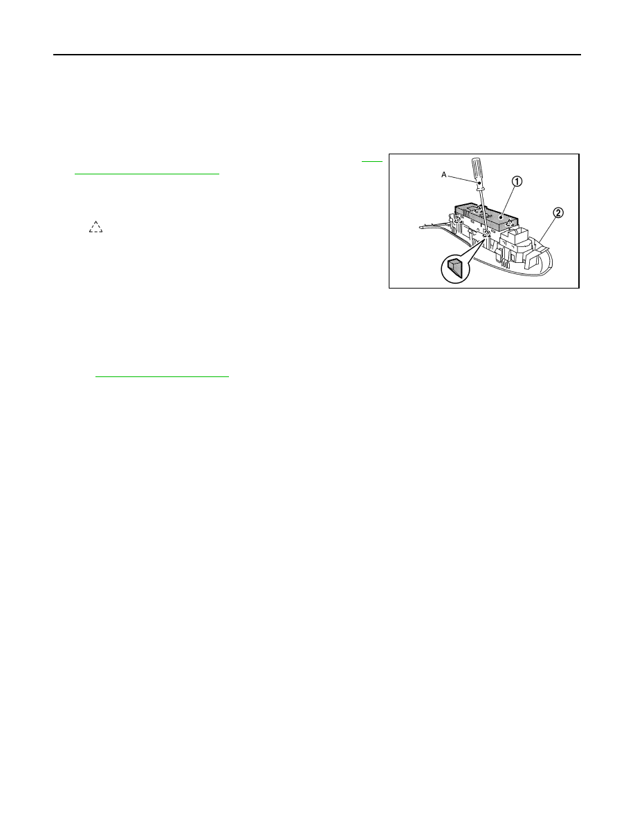
2.
Remove power window main switch (1) from power window
main switch finisher (2) using a remover tool (A).
NOTE:
The same procedure is also performed for front power window
switch (passenger side).
INSTALLATION
Install in the reverse order of removal.
NOTE:
If power window main switch or front power window (passenger side) is replaced or is removed, it is necessary
to perform the initialization procedure.
Refer to
: Pawl
JMKIA8164ZZ