Nissan Quest E52. Manual - part 930
PCS
IPDM E/R
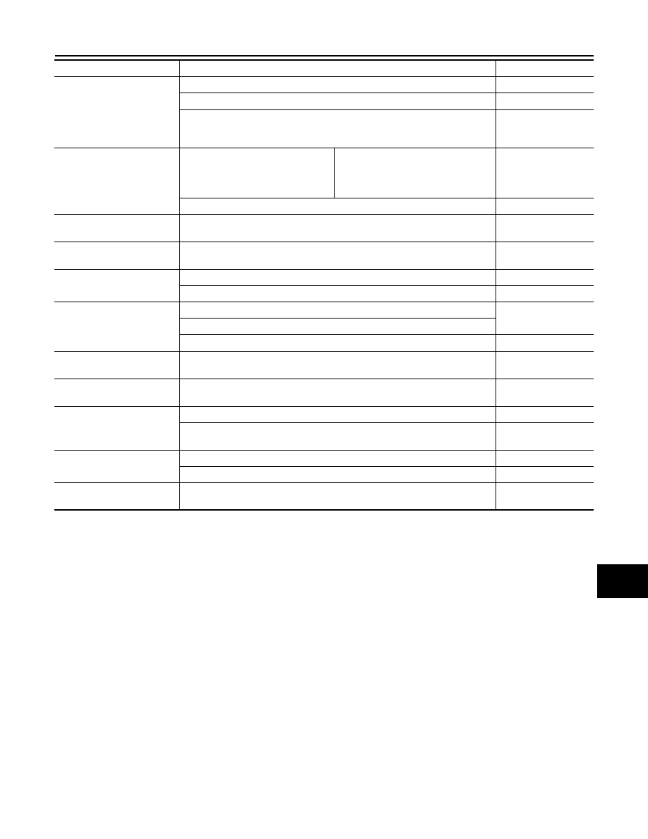
PCS-17
< ECU DIAGNOSIS INFORMATION >
[IPDM E/R]
C
D
E
F
G
H
I
J
K
L
B
A
O
P
N
ST/INHI RLY
Ignition switch ON
Off
At engine cranking
INHI
→
ST
The status of starter relay or starter control relay cannot be recognized by the
battery voltage malfunction, etc. when the starter relay is ON and the starter
control relay is OFF
UNKWN
DETENT SW
Ignition switch ON
• Press the selector button with selec-
tor lever in P position
• Selector lever in any position other
than P
Off
Release the selector button with selector lever in P position
On
S/L RLY -REQ
NOTE:
The item is indicated, but not monitored.
Off
S/L STATE
NOTE:
The item is indicated, but not monitored.
UNLK
DTRL REQ
Daytime running light system is not operated
Off
Daytime running light system is operated
On
OIL P SW
Ignition switch OFF or ACC
Open
Ignition switch ON (engine running)
Ignition switch ON (engine stopped)
Close
HOOD SW
NOTE:
The item is indicated, but not monitored.
Off
HL WASHER REQ
NOTE:
The item is indicated, but not monitored.
Off
THFT HRN REQ
Not operation
Off
• Panic alarm is activated
• Theft warning alarm is activated
On
HORN CHIRP
Not operation
Off
Door locking with Intelligent Key (horn chirp mode)
On
CRNRNG LMP REQ
NOTE:
The item is indicated, but not monitored.
Off
Monitor Item
Condition
Value/Status