Nissan Quest E52. Manual - part 866


  Index      Nissan     Nissan Quest E52 (2011-2014 year) - Service and Repair Manual


Search            


Content   ..  864  865  866  867   ..


Nissan Quest E52. Manual - part 866


LAN-178

< DTC/CIRCUIT DIAGNOSIS >

[CAN SYSTEM (TYPE 6)]

MAIN LINE BETWEEN ADP AND ASD-L CIRCUIT

MAIN LINE BETWEEN ADP AND ASD-L CIRCUIT

Diagnosis Procedure

INFOID:0000000009979391

1.

CHECK HARNESS CONTINUITY (OPEN CIRCUIT)

1.

Turn the ignition switch OFF.

2.

Disconnect the battery cable from the negative terminal.

3.

Disconnect the following harness connectors.

-

ECM

-

Harness connectors B530 and B89

-

Sliding door control unit LH

4.

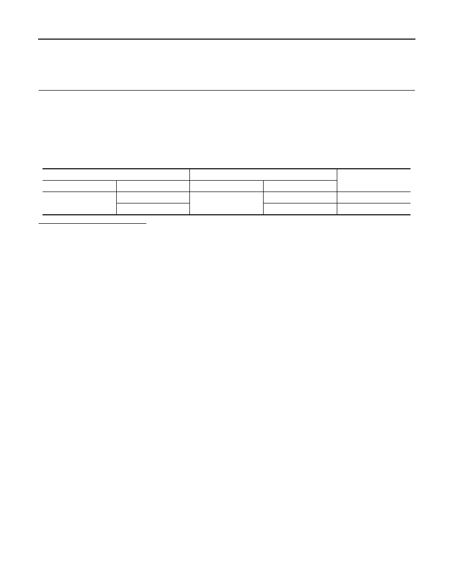
Check the continuity between the harness connector and the sliding door control unit LH harness connec-
tor.

Is the inspection result normal?

YES (Present error)>>Check CAN system type decision again.
YES (Past error)>>Error was detected in the main line between the driver seat control unit and the sliding

door control unit LH. 

NO

>> Repair the main line between the harness connector B89 and the sliding door control unit LH.

Harness connector

Sliding door control unit LH harness connector

Continuity

Connector No.

Terminal No.

Connector No.

Terminal No.

B89

13

B45

10

Existed

12

9

Existed

LAN

ECM BRANCH LINE CIRCUIT

LAN-179

< DTC/CIRCUIT DIAGNOSIS >

[CAN SYSTEM (TYPE 6)]

C

D

E

F

G

H

I

J

K

L

B

A

O

P

N

ECM BRANCH LINE CIRCUIT

Diagnosis Procedure

INFOID:0000000009979393

1.

CHECK CONNECTOR

1.

Turn the ignition switch OFF.

2.

Disconnect the battery cable from the negative terminal.

3.

Check the terminals and connectors of the ECM for damage, bend and loose connection (unit side and
connector side).

Is the inspection result normal?

YES

>> GO TO 2.

NO

>> Repair the terminal and connector.

2.

CHECK HARNESS FOR OPEN CIRCUIT

1.

Disconnect the connector of ECM.

2.

Check the resistance between the ECM harness connector terminals.

Is the measurement value within the specification?

YES

>> GO TO 3.

NO

>> Repair the ECM branch line.

3.

CHECK POWER SUPPLY AND GROUND CIRCUIT

Check the power supply and the ground circuit of the ECM. Refer to 

EC-163, "Diagnosis Procedure"

.

Is the inspection result normal?

YES (Present error)>>Replace the ECM. Refer to the 

EC-460, "Removal and Installation"

.

YES (Past error)>>Error was detected in the ECM branch line.
NO

>> Repair the power supply and the ground circuit.

ECM harness connector

Resistance (

)

Connector No.

Terminal No.

E16

114

113

Approx. 108 – 132

LAN-180

< DTC/CIRCUIT DIAGNOSIS >

[CAN SYSTEM (TYPE 6)]

EPS BRANCH LINE CIRCUIT

EPS BRANCH LINE CIRCUIT

Diagnosis Procedure

INFOID:0000000009979394

1.

CHECK CONNECTOR

1.

Turn the ignition switch OFF.

2.

Disconnect the battery cable from the negative terminal.

3.

Check the terminals and connectors of the power steering control module for damage, bend and loose
connection (unit side and connector side).

Is the inspection result normal?

YES

>> GO TO 2.

NO

>> Repair the terminal and connector.

2.

CHECK HARNESS FOR OPEN CIRCUIT

1.

Disconnect the connector of power steering control module.

2.

Check the resistance between the power steering control module harness connector terminals.

Is the measurement value within the specification?

YES

>> GO TO 3.

NO

>> Repair the power steering control module branch line.

3.

CHECK POWER SUPPLY AND GROUND CIRCUIT

Check the power supply and the ground circuit of the power steering control module. Refer to 

STC-21, "Diag-

nosis Procedure"

.

Is the inspection result normal?

YES (Present error)>>Replace the power steering oil pump assembly. Refer to 

ST-32, "Removal and Instal-

lation"

.

YES (Past error)>>Error was detected in the power steering control module branch line.
NO

>> Repair the power supply and the ground circuit.

Power steering control module harness connector

Resistance (

)

Connector No.

Terminal No.

E34

8

7

Approx. 54 – 66

LAN

ABS BRANCH LINE CIRCUIT

LAN-181

< DTC/CIRCUIT DIAGNOSIS >

[CAN SYSTEM (TYPE 6)]

C

D

E

F

G

H

I

J

K

L

B

A

O

P

N

ABS BRANCH LINE CIRCUIT

Diagnosis Procedure

INFOID:0000000009979395

1.

CHECK CONNECTOR

1.

Turn the ignition switch OFF.

2.

Disconnect the battery cable from the negative terminal.

3.

Check the terminals and connectors of the ABS actuator and electric unit (control unit) for damage, bend
and loose connection (unit side and connector side).

Is the inspection result normal?

YES

>> GO TO 2.

NO

>> Repair the terminal and connector.

2.

CHECK HARNESS FOR OPEN CIRCUIT

1.

Disconnect the connector of ABS actuator and electric unit (control unit).

2.

Check the resistance between the ABS actuator and electric unit (control unit) harness connector termi-
nals.

Is the measurement value within the specification?

YES

>> GO TO 3.

NO

>> Repair the ABS actuator and electric unit (control unit) branch line.

3.

CHECK POWER SUPPLY AND GROUND CIRCUIT

Check the power supply and the ground circuit of the ABS actuator and electric unit (control unit). Refer to

BRC-101, "Diagnosis Procedure"

.

Is the inspection result normal?

YES (Present error)>>Replace the ABS actuator and electric unit (control unit). Refer to 

BRC-123, "Removal

and Installation"

.

YES (Past error)>>Error was detected in the ABS actuator and electric unit (control unit) branch line.
NO

>> Repair the power supply and the ground circuit.

ABS actuator and electric unit (control unit) harness connector

Resistance (

)

Connector No.

Terminal No.

E36

23

21

Approx. 54 – 66


Content   ..  864  865  866  867   ..