Nissan Quest E52. Manual - part 846


  Index      Nissan     Nissan Quest E52 (2011-2014 year) - Service and Repair Manual


Search            


Content   ..  844  845  846  847   ..


Nissan Quest E52. Manual - part 846


LAN-98

< DTC/CIRCUIT DIAGNOSIS >

[CAN SYSTEM (TYPE 2)]

ECM BRANCH LINE CIRCUIT

ECM BRANCH LINE CIRCUIT

Diagnosis Procedure

INFOID:0000000009978235

1.

CHECK CONNECTOR

1.

Turn the ignition switch OFF.

2.

Disconnect the battery cable from the negative terminal.

3.

Check the terminals and connectors of the ECM for damage, bend and loose connection (unit side and
connector side).

Is the inspection result normal?

YES

>> GO TO 2.

NO

>> Repair the terminal and connector.

2.

CHECK HARNESS FOR OPEN CIRCUIT

1.

Disconnect the connector of ECM.

2.

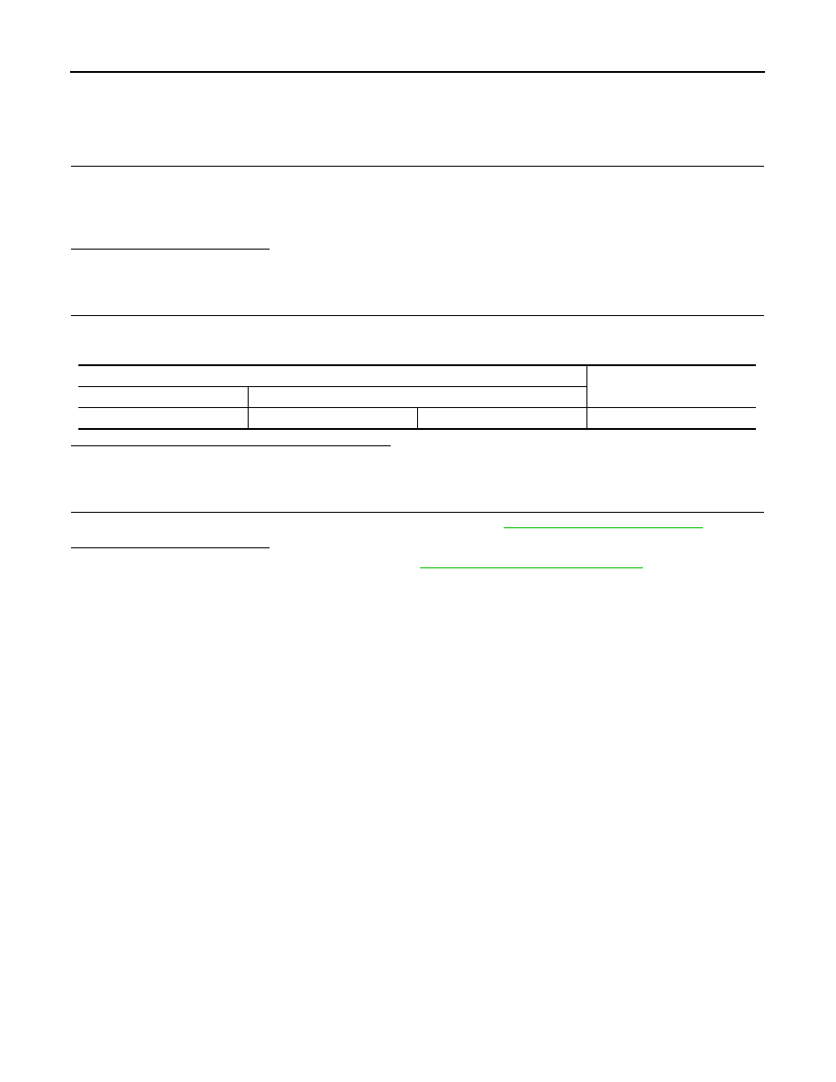
Check the resistance between the ECM harness connector terminals.

Is the measurement value within the specification?

YES

>> GO TO 3.

NO

>> Repair the ECM branch line.

3.

CHECK POWER SUPPLY AND GROUND CIRCUIT

Check the power supply and the ground circuit of the ECM. Refer to 

EC-163, "Diagnosis Procedure"

.

Is the inspection result normal?

YES (Present error)>>Replace the ECM. Refer to the 

EC-460, "Removal and Installation"

.

YES (Past error)>>Error was detected in the ECM branch line.
NO

>> Repair the power supply and the ground circuit.

ECM harness connector

Resistance (

)

Connector No.

Terminal No.

E16

114

113

Approx. 108 – 132

LAN

EPS BRANCH LINE CIRCUIT

LAN-99

< DTC/CIRCUIT DIAGNOSIS >

[CAN SYSTEM (TYPE 2)]

C

D

E

F

G

H

I

J

K

L

B

A

O

P

N

EPS BRANCH LINE CIRCUIT

Diagnosis Procedure

INFOID:0000000009978236

1.

CHECK CONNECTOR

1.

Turn the ignition switch OFF.

2.

Disconnect the battery cable from the negative terminal.

3.

Check the terminals and connectors of the power steering control module for damage, bend and loose
connection (unit side and connector side).

Is the inspection result normal?

YES

>> GO TO 2.

NO

>> Repair the terminal and connector.

2.

CHECK HARNESS FOR OPEN CIRCUIT

1.

Disconnect the connector of power steering control module.

2.

Check the resistance between the power steering control module harness connector terminals.

Is the measurement value within the specification?

YES

>> GO TO 3.

NO

>> Repair the power steering control module branch line.

3.

CHECK POWER SUPPLY AND GROUND CIRCUIT

Check the power supply and the ground circuit of the power steering control module. Refer to 

STC-21, "Diag-

nosis Procedure"

.

Is the inspection result normal?

YES (Present error)>>Replace the power steering oil pump assembly. Refer to 

ST-32, "Removal and Instal-

lation"

.

YES (Past error)>>Error was detected in the power steering control module branch line.
NO

>> Repair the power supply and the ground circuit.

Power steering control module harness connector

Resistance (

)

Connector No.

Terminal No.

E34

8

7

Approx. 54 – 66

LAN-100

< DTC/CIRCUIT DIAGNOSIS >

[CAN SYSTEM (TYPE 2)]

ABS BRANCH LINE CIRCUIT

ABS BRANCH LINE CIRCUIT

Diagnosis Procedure

INFOID:0000000009978237

1.

CHECK CONNECTOR

1.

Turn the ignition switch OFF.

2.

Disconnect the battery cable from the negative terminal.

3.

Check the terminals and connectors of the ABS actuator and electric unit (control unit) for damage, bend
and loose connection (unit side and connector side).

Is the inspection result normal?

YES

>> GO TO 2.

NO

>> Repair the terminal and connector.

2.

CHECK HARNESS FOR OPEN CIRCUIT

1.

Disconnect the connector of ABS actuator and electric unit (control unit).

2.

Check the resistance between the ABS actuator and electric unit (control unit) harness connector termi-
nals.

Is the measurement value within the specification?

YES

>> GO TO 3.

NO

>> Repair the ABS actuator and electric unit (control unit) branch line.

3.

CHECK POWER SUPPLY AND GROUND CIRCUIT

Check the power supply and the ground circuit of the ABS actuator and electric unit (control unit). Refer to

BRC-101, "Diagnosis Procedure"

.

Is the inspection result normal?

YES (Present error)>>Replace the ABS actuator and electric unit (control unit). Refer to 

BRC-123, "Removal

and Installation"

.

YES (Past error)>>Error was detected in the ABS actuator and electric unit (control unit) branch line.
NO

>> Repair the power supply and the ground circuit.

ABS actuator and electric unit (control unit) harness connector

Resistance (

)

Connector No.

Terminal No.

E36

23

21

Approx. 54 – 66

LAN

TCM BRANCH LINE CIRCUIT

LAN-101

< DTC/CIRCUIT DIAGNOSIS >

[CAN SYSTEM (TYPE 2)]

C

D

E

F

G

H

I

J

K

L

B

A

O

P

N

TCM BRANCH LINE CIRCUIT

Diagnosis Procedure

INFOID:0000000009978238

1.

CHECK CONNECTOR

1.

Turn the ignition switch OFF.

2.

Disconnect the battery cable from the negative terminal.

3.

Check the following terminals and connectors for damage, bend and loose connection (unit side and con-
nector side).

-

TCM

-

Harness connector F123

-

Harness connector E6

Is the inspection result normal?

YES

>> GO TO 2.

NO

>> Repair the terminal and connector.

2.

CHECK HARNESS FOR OPEN CIRCUIT

1.

Disconnect the connector of TCM.

2.

Check the resistance between the TCM harness connector terminals.

Is the measurement value within the specification?

YES

>> GO TO 3.

NO

>> Repair the TCM branch line.

3.

CHECK POWER SUPPLY AND GROUND CIRCUIT

Check the power supply and the ground circuit of the TCM. Refer to 

TM-114, "Diagnosis Procedure"

.

Is the inspection result normal?

YES (Present error)>>Replace the TCM. Refer to 

TM-158, "Removal and Installation"

.

YES (Past error)>>Error was detected in the TCM branch line.
NO

>> Repair the power supply and the ground circuit.

TCM harness connector

Resistance (

)

Connector No.

Terminal No.

F23

32

31

Approx. 54 – 66


Content   ..  844  845  846  847   ..