Nissan Quest E52. Manual - part 833


  Index      Nissan     Nissan Quest E52 (2011-2014 year) - Service and Repair Manual


Search            


Content   ..  831  832  833  834   ..


Nissan Quest E52. Manual - part 833


LAN-46

< DTC/CIRCUIT DIAGNOSIS >

[CAN]

MALFUNCTION AREA CHART

DTC/CIRCUIT DIAGNOSIS

MALFUNCTION AREA CHART

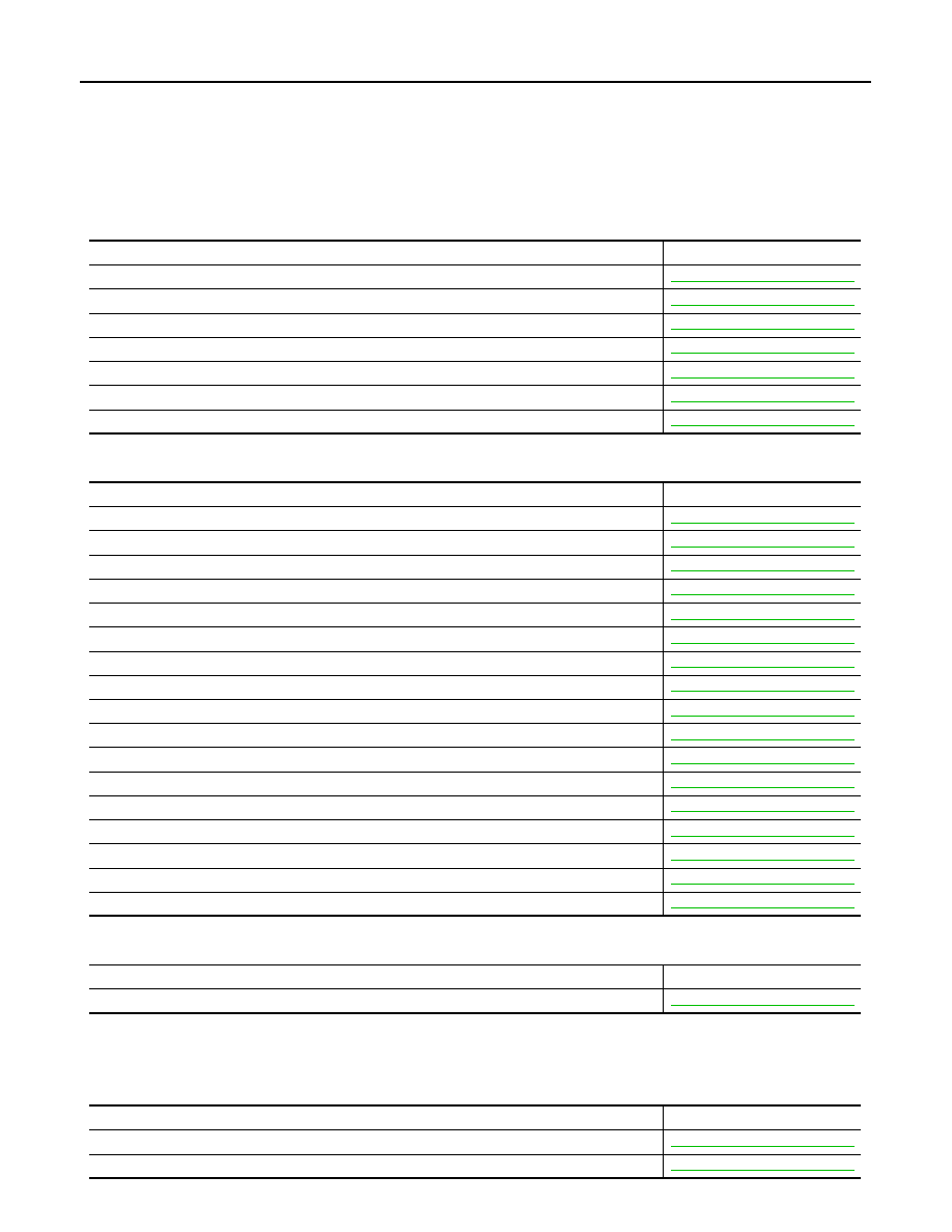
CAN Communication Circuit

INFOID:0000000009653542

MAIN LINE

BRANCH LINE

SHORT CIRCUIT

BSW Communication Circuit

INFOID:0000000009653543

BRANCH LINE

Malfunction area

Reference

Main line between power steering control module and ABS actuator and electric unit (control unit)

LAN-48, "Diagnosis Procedure"

Main line between ABS actuator and electric unit (control unit) and data link connector

LAN-49, "Diagnosis Procedure"

Main line between data link connector and air bag diagnosis sensor unit

LAN-50, "Diagnosis Procedure"

Main line between air bag diagnosis sensor unit and sliding door control unit RH

LAN-51, "Diagnosis Procedure"

Main line between sliding door control unit RH and sliding door control unit LH

LAN-52, "Diagnosis Procedure"

Main line between sliding door control unit RH and driver seat control unit

LAN-53, "Diagnosis Procedure"

Main line between driver seat control unit and sliding door control unit LH

LAN-54, "Diagnosis Procedure"

Malfunction area

Reference

ECM branch line circuit 

LAN-55, "Diagnosis Procedure"

Power steering control module branch line circuit 

LAN-56, "Diagnosis Procedure"

ABS actuator and electric unit (control unit) branch line circuit 

LAN-57, "Diagnosis Procedure"

TCM branch line circuit

LAN-58, "Diagnosis Procedure"

BCM branch line circuit 

LAN-59, "Diagnosis Procedure"

Data link connector branch line circuit 

LAN-60, "Diagnosis Procedure"

Combination meter branch line circuit 

LAN-61, "Diagnosis Procedure"

Steering angle sensor branch line circuit 

LAN-62, "Diagnosis Procedure"

Air bag diagnosis sensor unit branch line circuit 

LAN-63, "Diagnosis Procedure"

AV control unit branch line circuit

LAN-64, "Diagnosis Procedure"

Around view monitor control unit

LAN-65, "Diagnosis Procedure"

BSW control module branch line circuit

LAN-66, "Diagnosis Procedure"

Sliding door control unit RH branch line circuit

LAN-67, "Diagnosis Procedure"

Driver seat control unit branch line circuit

LAN-68, "Diagnosis Procedure"

Sliding door control unit LH branch line circuit

LAN-69, "Diagnosis Procedure"

Automatic back door control module branch line circuit

LAN-70, "Diagnosis Procedure"

IPDM E/R branch line circuit 

LAN-71, "Diagnosis Procedure"

Malfunction area

Reference

CAN communication circuit

LAN-74, "Diagnosis Procedure"

Malfunction area

Reference

Side radar LH branch line circuit

LAN-72, "Diagnosis Procedure"

Side radar RH branch line circuit

LAN-73, "Diagnosis Procedure"

LAN

MALFUNCTION AREA CHART

LAN-47

< DTC/CIRCUIT DIAGNOSIS >

[CAN]

C

D

E

F

G

H

I

J

K

L

B

A

O

P

N

SHORT CIRCUIT OR OPEN CIRCUIT

Malfunction area

Reference

BSW communication circuit

LAN-76, "Diagnosis Procedure"

LAN-48

< DTC/CIRCUIT DIAGNOSIS >

[CAN]

MAIN LINE BETWEEN EPS AND ABS CIRCUIT

MAIN LINE BETWEEN EPS AND ABS CIRCUIT

Diagnosis Procedure

INFOID:0000000009653544

1.

CHECK HARNESS CONTINUITY (OPEN CIRCUIT)

1.

Turn the ignition switch OFF.

2.

Disconnect the battery cable from the negative terminal.

3.

Disconnect the following harness connectors.

-

ECM

-

Power steering control module

-

ABS actuator and electric unit (control unit)

4.

Check the continuity between the power steering control module harness connector and the ABS actuator
and electric unit (control unit) harness connector.

Is the inspection result normal?

YES (Present error)>>Check CAN system type decision again.
YES (Past error)>>Error was detected in the main line between the power steering control module and the

ABS actuator and electric unit (control unit). 

NO

>> Repair the main line between the power steering control module and the ABS actuator and elec-

tric unit (control unit).

Power steering control module harness connector

ABS actuator and electric unit (control unit) harness 

connector

Continuity

Connector No.

Terminal No.

Connector No.

Terminal No.

E34

8

E36

23

Existed

7

21

Existed

LAN

MAIN LINE BETWEEN ABS AND DLC CIRCUIT

LAN-49

< DTC/CIRCUIT DIAGNOSIS >

[CAN]

C

D

E

F

G

H

I

J

K

L

B

A

O

P

N

MAIN LINE BETWEEN ABS AND DLC CIRCUIT

Diagnosis Procedure

INFOID:0000000009653545

1.

CHECK CONNECTOR

1.

Turn the ignition switch OFF.

2.

Disconnect the battery cable from the negative terminal.

3.

Check the following terminals and connectors for damage, bend and loose connection (connector side
and harness side).

-

Harness connector E105

-

Harness connector M11

Is the inspection result normal?

YES

>> GO TO 2.

NO

>> Repair the terminal and connector.

2.

CHECK HARNESS CONTINUITY (OPEN CIRCUIT)

1.

Disconnect the following harness connectors.

-

ABS actuator and electric unit (control unit)

-

Harness connectors E105 and M11

2.

Check the continuity between the ABS actuator and electric unit (control unit) harness connector and the
harness connector.

Is the inspection result normal?

YES

>> GO TO 3.

NO

>> Repair the main line between the ABS actuator and electric unit (control unit) and the harness

connector E105.

3.

CHECK HARNESS CONTINUITY (OPEN CIRCUIT)

Check the continuity between the harness connector and the data link connector.

Is the inspection result normal?

YES (Present error)>>Check CAN system type decision again.
YES (Past error)>>Error was detected in the main line between the ABS actuator and electric unit (control

unit) and the data link connector. 

NO

>> Repair the main line between the harness connector M11 and the data link connector.

ABS actuator and electric unit (control unit) harness 

connector

Harness connector

Continuity

Connector No.

Terminal No.

Connector No.

Terminal No.

E36

23

E105

14

Existed

21

15

Existed

Harness connector

Data link connector

Continuity

Connector No.

Terminal No.

Connector No.

Terminal No.

M11

14

M4

6

Existed

15

14

Existed


Content   ..  831  832  833  834   ..