Nissan Quest E52. Manual - part 784


  Index      Nissan     Nissan Quest E52 (2011-2014 year) - Service and Repair Manual


Search            


Content   ..  782  783  784  785   ..


Nissan Quest E52. Manual - part 784


INL-16

< SYSTEM DESCRIPTION >

SYSTEM

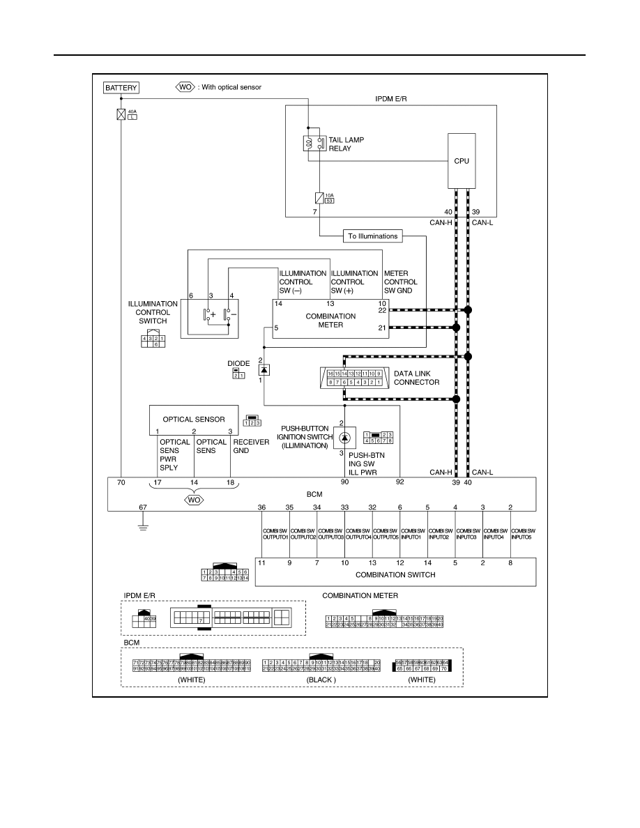
ILLUMINATION CONTROL SYSTEM : Circuit Diagram

INFOID:0000000009653471

AUTO LIGHT ADJUSTMENT SYSTEM

JMLIA4605GB

SYSTEM

INL-17

< SYSTEM DESCRIPTION >

C

D

E

F

G

H

I

J

K

M

A

B

INL

N

O

P

AUTO LIGHT ADJUSTMENT SYSTEM : System Description

INFOID:0000000009653472

SYSTEM DIAGRAM

OUTLINE

 Auto light adjustment system is controlled by each function of BCM, combination meter and AV control unit

Control by BCM

• Auto light system
• Auto light adjustment system

AUTO LIGHT ADJUSTMENT SYSTEM

Description

• BCM supplies voltage to the optical sensor when the ignition switch is turned ON or ACC.
• Optical sensor converts outside brightness (lux) to voltage and transmits the optical sensor signal to BCM.
• BCM judges dimming/brightening of combination meter and display according to brightness outside the vehi-

cle, when ignition switch is ON.

• BCM transmits dimmer signal to combination meter via CAN communication, according to auto light adjust-

ment conditions (Except for CANADA). Dimmer signal is also transmitted to AV control unit.

NOTE:
As to dimming/brightening timing, the sensitivity depends on settings. The settings can be changed with CON-
SULT. Refer to 

EXL-32, "HEADLAMP : CONSULT Function (BCM - HEADLAMP) (Xenon Type Headlamp)"

.

JMLIA0967GB

INL-18

< SYSTEM DESCRIPTION >

SYSTEM

AUTO LIGHT ADJUSTMENT SYSTEM : Circuit Diagram

INFOID:0000000009653473

JMLIA2130GB

DIAGNOSIS SYSTEM (BCM)

INL-19

< SYSTEM DESCRIPTION >

C

D

E

F

G

H

I

J

K

M

A

B

INL

N

O

P

DIAGNOSIS SYSTEM (BCM)

COMMON ITEM

COMMON ITEM : CONSULT Function (BCM - COMMON ITEM)

INFOID:0000000009980892

APPLICATION ITEM

CONSULT performs the following functions via CAN communication with BCM.

SYSTEM APPLICATION

BCM can perform the following functions for each system.
NOTE:
It can perform the diagnosis modes except the following for all sub system selection items.

×

: Applicable item

NOTE:

*: For models with automatic air conditioning control system, this diagnosis mode is not used.

FREEZE FRAME DATA (FFD)

The BCM records the following vehicle condition at the time a particular DTC is detected, and displays on
CONSULT.

Diagnosis mode

Function Description

Work Support

Changes the setting for each system function.

Self Diagnostic Result

Displays the diagnosis results judged by BCM.

CAN Diag Support Monitor

Monitors the reception status of CAN communication viewed from BCM.

Data Monitor

The BCM input/output signals are displayed.

Active Test

The signals used to activate each device are forcibly supplied from BCM.

Ecu Identification

The BCM part number is displayed.

Configuration

• Read and save the vehicle specification.
• Write the vehicle specification when replacing BCM.

System

Sub system selection item

Diagnosis mode

Work Support

Data Monitor

Active Test

Door lock

DOOR LOCK

×

×

×

Rear window defogger

REAR DEFOGGER

×

×

Warning chime

BUZZER

×

×

Interior room lamp control system

INT LAMP

×

×

×

Exterior lamp

HEAD LAMP

×

×

×

Wiper and washer

WIPER

×

×

×

Turn signal and hazard warning lamps

FLASHER

×

×

×

Air conditioning control system

AIR CONDITONER

×

×

*

• Intelligent Key system
• Engine start system

INTELLIGENT KEY

×

×

×

Combination switch

COMB SW

×

Body control system

BCM

×

NVIS

IMMU

×

×

×

Interior room lamp battery saver

BATTERY SAVER

×

×

×

Back door open

TRUNK

×

Vehicle security system

THEFT ALM

×

×

×

RAP system

RETAINED PWR

×

Signal buffer system

SIGNAL BUFFER

×

×

TPMS

AIR PRESSURE MONITOR

×

×

×


Content   ..  782  783  784  785   ..