Nissan Quest E52. Manual - part 774
HAC-226
< DTC/CIRCUIT DIAGNOSIS >
[MANUAL AIR CONDITIONING]
REAR BLOWER MOTOR
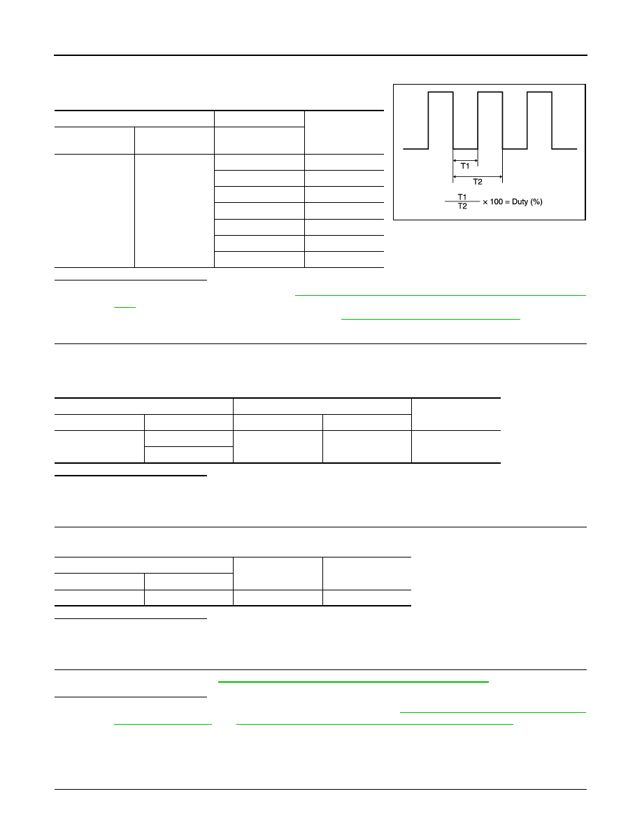
NOTE:
Calculate drive signal duty ratio as shown in the figure.
T2 = Approx. 1.6 ms
Is the inspection result normal?
YES
>> Replace rear blower motor. Refer to
VTL-18, "REAR BLOWER MOTOR : Removal and Installa-
.
NO
>> Replace front A/C control (A/C amp.). Refer to
HAC-238, "Removal and Installation"
.
6.
CHECK REAR BLOWER MOTOR POWER SUPPLY CIRCUIT FOR OPEN
1.
Turn ignition switch OFF.
2.
Disconnect rear blower relay connector.
3.
Check continuity between rear blower relay harness connector and rear blower motor harness connector.
Is the inspection result normal?
YES
>> GO TO 7.
NO
>> Repair harness or connector.
7.
CHECK REAR BLOWER RELAY GROUND CIRCUIT FOR OPEN
Check continuity between rear blower relay harness connector and ground.
Is the inspection result normal?
YES
>> GO TO 8.
NO
>> Repair harness or connector.
8.
CHECK REAR BLOWER RELAY
Check rear blower relay. Refer to
HAC-227, "Component Inspection (Rear Blower Relay)"
.
Is the inspection result normal?
YES
>> Check rear blower relay power supply circuit. Refer to
PG-11, "Wiring Diagram - BATTERY
PG-54, "Wiring Diagram - IGNITION POWER SUPPLY -"
NO
>> Replace rear blower relay.
Component Inspection (Rear Blower Motor)
INFOID:0000000009652666
1.
CHECK REAR BLOWER MOTOR-I
Rear blower motor
Condition
Duty ratio
(Approx.)
Connector
Terminal
Fan speed
VENT mode
B403
2
1st
25 %
2nd
33 %
3rd
41 %
4th
51 %
5th
61 %
6th
69 %
7th
81 %
JPLIA1210GB
Rear blower relay
Rear blower motor
Continuity
Connector
Terminal
Connector
Terminal
M14
5
B403
3
Existed
7
Rear blower relay
—
Continuity
Connector
Terminal
M14
2
Ground
Existed